Our company adopts the world's advanced level of software packages and CFD flow field analysis software for design, to ensure that the product operating conditions of high efficiency without harmful pressure fluctuations, vibration or resonance. In recent years, more than 600 hydropower stations around the country have successfully implemented the efficiency expansion and technical upgrading, with good results, well received by users!
The electrical system of a hydropower station can generally be divided into several parts, such as hydroelectric generators, generator voltage equipment, main transformers, high-voltage power distribution devices, auxiliary power systems, and grounding systems, as shown by the solid line boxes in the following figure.
The hydroelectric generator and the main electrical wiring are like the heart and aorta of the electrical system. The hydroelectric generator converts the rotating mechanical energy output by the hydro turbine into electrical energy, which is the source of the electrical energy output of the hydropower station. The efficiency of large hydro-generators can generally reach about 98%. At present, the maximum capacity of hydroelectric generators in operation in China is 889MVA. The electrical main wiring is to connect the hydroelectric generator, generator voltage equipment, main transformer, high voltage distribution device, power system, etc. in an appropriate way to achieve the functions of electric energy transmission, boost, collection, distribution, and sending .
The generator voltage equipment transmits the electrical energy generated by the hydroelectric generator to the main transformer. The return flow has the characteristics of high voltage and high current. The auxiliary power system and the excitation device of the unit are generally connected to the power supply from here. At present, the voltage levels of generators in hydropower stations have been put into operation up to 24kV. Considering the factors such as the peak participation of the hydropower station and the frequent switching of the unit, the generator-generator circuit breaker is often installed at the outlet of the turbine generator. The connecting conductor of the voltage loop of the generator of the large-capacity unit is usually a closed-phase bus.
The main transformer is the junction of the generator voltage equipment and the high-voltage power distribution device. It raises the generator voltage to the transmission voltage to reduce the transmission current, thereby effectively reducing the transmission loss and material cost of the power grid. In general, the larger the installed capacity and the longer the transmission distance, the higher the transmission voltage. At present, the transmission voltage level of hydropower stations in China is up to 750kV.
The high-voltage power distribution device is used to collect the electrical energy sent by the main transformer and send it to the power system through the outlet field. It mainly includes three types of open power distribution device, gas insulated metal enclosed switchgear (GIS) and hybrid power distribution device. Since most hydropower stations are located in high mountain and canyon areas, the layout of high-voltage distribution devices is often restricted. Therefore, GIS with the highest reliability and the most compact layout but relatively high cost has become the first choice for high-voltage distribution devices in hydropower stations in China. 800kV. High-voltage outgoing lines of hydropower stations usually use high-voltage power cables or gas-insulated metal enclosed transmission lines (GIL).
The plant power system obtains power from units, power grids, etc., and provides power to loads (points) such as power plant unit operations, lighting, public equipment, and dam area power equipment according to the needs of power facilities. The grounding system is used to ensure the normal operation of the electrical system of the hydropower station and the safety of people and equipment. At present, the grounding system of the hydropower station makes full use of the reservoir water, underwater steel structure and natural grounding body to reduce the grounding resistance. Auxiliary power system and grounding system are important guarantees for the safety, reliability and economic operation of hydropower stations. Their equipment and wiring are widely distributed in various parts of hydropower stations.

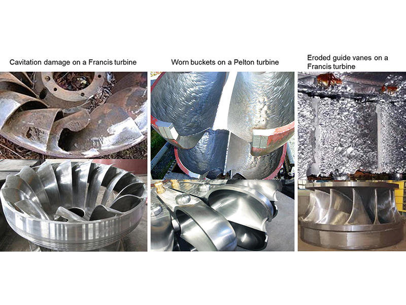
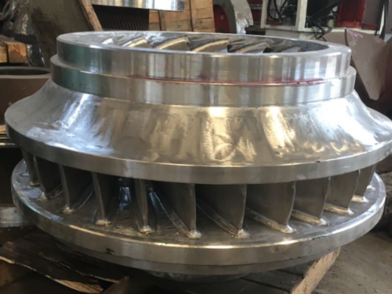
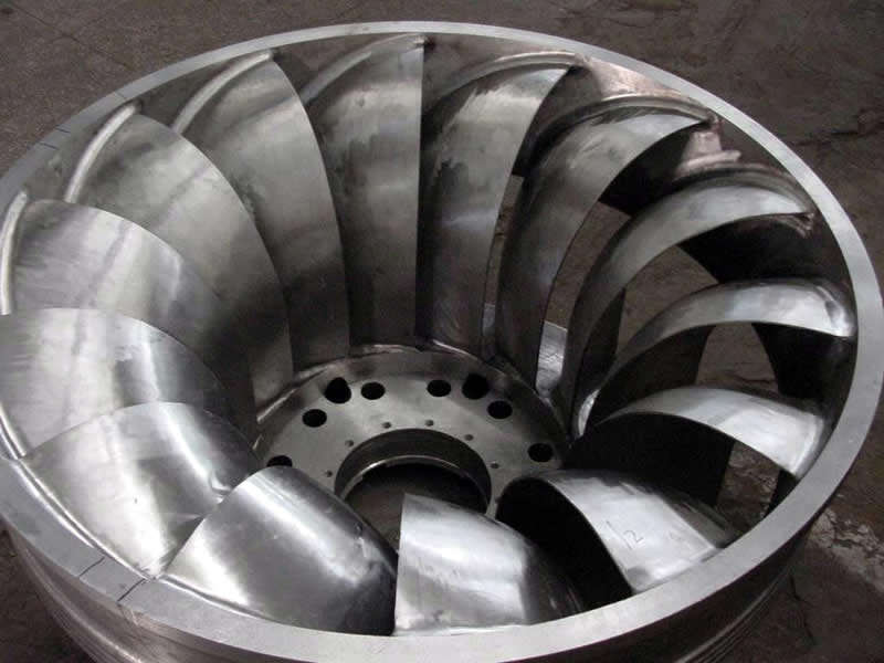
Francis type units cover a head range from 40 to 600 m (130 to 2,000 ft), and their connected generator output power varies from just a few kilowatts up to 800 MW. Large Francis turbines are individually designed for each site to operate with the given water supply and water head at the highest possible efficiency, typically over 90%.
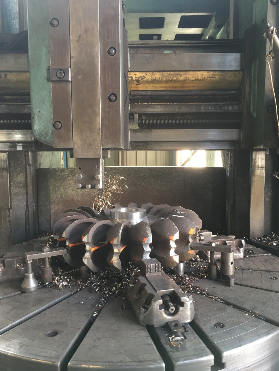
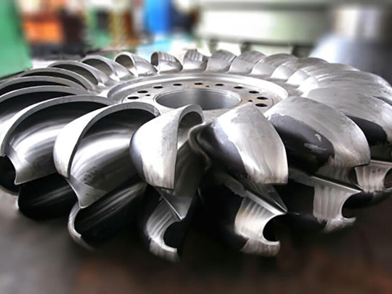
Pelton runner operate best with heads from 15–1,800 metres (50–5,910 ft)
The pressure regulating valve is a safety device of the long pressure diversion tunnel hydropower station. Generally, when the pressure diversion pipeline ΣLV / H is greater than 15 to 30, a surge tank should be installed. Due to the large amount of civil engineering works and the long construction period, the use of a pressure regulating valve instead of a pressure regulating well can save investment and shorten the construction period.
The main body of the pressure regulating valve is arranged horizontally, that is, the center lines of the water inlet pipe and the oil cylinder are parallel to the ground, mainly composed of the valve housing, the valve plug, the main oil cylinder, the guide oil cylinder, and the air supplement valve.
The valve housing is welded or cast steel. It is composed of two semi-volute tubes symmetrical left and right. There are three open holes, one end is the water inlet, the other end is the water outlet, and the other end is reserved for connection with the main cylinder. There are fixed guide vanes in the volute tube of the valve housing, so that after the water enters, it forms a circular flow and collides with each other in the valve body to dissipate energy, and then discharges to the tail water, which has good energy dissipation performance. In order to reduce vibration, an air supplement device is provided so that the atmosphere can evenly enter the negative pressure area at the inlet end of the discharge channel of the pressure regulating valve.
The valve plug is made of cast steel with chrome-plated surface to prevent rust. The valve plug is provided with pressure equalizing holes. The purpose is to balance the water pressure on both sides of the valve plug to reduce the operating oil pressure.
The main oil cylinder and the guide oil cylinder are used to operate the switch of the valve plug. The cylinder is made of cast steel and has a piston. The oil source from the governor of the unit is connected to the front and rear chambers of the main oil cylinder piston respectively. When the unit is working normally , The pressure oil passes through the closing cavity, so that the pressure regulating valve is in the closed state; when the unit emergency shutdown or instantaneous load dump exceeds about 15%, the pressure oil will automatically pass through the opening cavity, so that the pressure regulating valve opens to release the set size Water flow to ensure the safety of the unit and pressure tunnel system.
The supplementary air valve is installed on the valve housing, which can make the atmosphere directly enter the negative pressure area at the inlet end of the drain channel of the pressure regulating valve when the pressure regulating valve is draining, so as to reduce the cavitation of the flow channel and reduce the pressure regulating valve. Vibration.
A hard seal is used between the valve plug and the valve housing, that is, a stainless steel water stop ring is fixed on the valve plug, and a removable stainless steel or bronze water stop is used on the valve housing (the stainless steel material with hardness different from the stainless steel on the valve plug is better ), Through fine grinding between the two to achieve close contact, with good water stopping properties. All parts that will move relatively between the cylinder barrel and the piston, between the piston rod and the valve housing are all sealed with a special rubber ring.
In order to realize the control of the pressure regulating valve, it is necessary to install a special main pressure control valve, a throttle valve and an oil pressure check valve for control in the hydraulic system. Among them, the special main pressure regulating valve is installed in the governor of the unit, which is the most reliable form of control with the pressure regulating valve governor. The structure of the special main pressure regulating valve is to add an additional valve disc to control the pressure regulating valve.
The characteristics of the pressure regulating valve are mainly flow characteristics (see the series of design data collection for details).
The function of the pressure regulating valve is to quickly open the pressure regulating valve at the same time when the unit guide vane is quickly closed when the unit is dumping the load, and to discharge the flow that needs to be reduced when the unit is closed from the pressure regulating valve. That is to say, after installing the pressure regulating valve, the flow rate change in the water diversion system can proceed slowly, thereby reducing the water pressure rise value. On the other hand, since the unit is still closed quickly, which ensures that the rate rise value will not be too high, the pressure regulating valve is one of the effective measures to reduce the pressure rise value of the diversion system and the unit rate rise value. The role of surge tank.
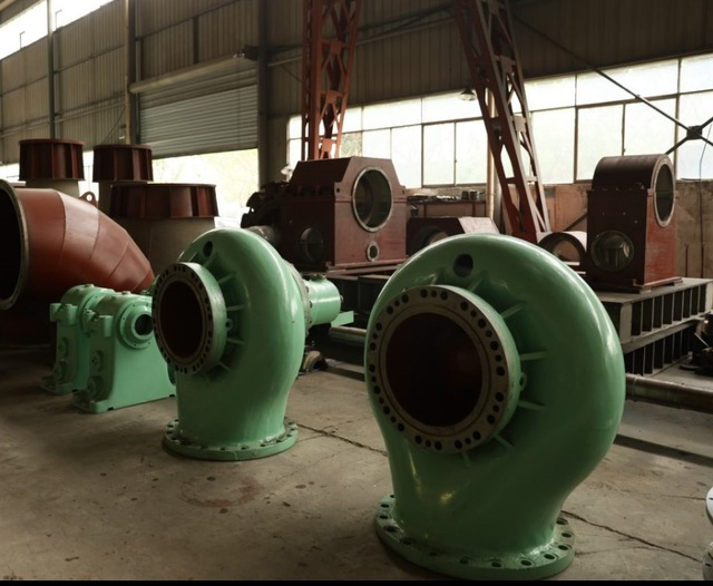
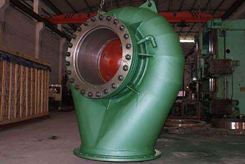
“Our rehabilitation and service experts let your proven hydropower asset shine with new brilliance.”
Every existing hydropower plant has its own specific operational history and defined future operational strategy. Today, solution-oriented service and rehabilitation concepts are needed to improve overall efficiency, reduce operational expenditures, extend lifetimes, and make hydropower plants fit for the future.
INCREASING ANNUAL POWER PRODUCTION
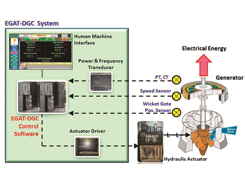
The efficiency of turbines and generators has significantly increased over the last few decades. As a result, refurbishments to upgrade a plant’s performance are possible and highly cost-effective. Depending on the circumstances, an upgrade of a 40-year-old turbine runner can offer up to 5% more efficiency and an even bigger increase in terms of annual energy production. The overall efficiency of a hydropower plant can be optimized using digital controllers, for example.
LIFETIME EXTENSION
As hydro equipment ages, wear and tear affects the plant efficiency. Aging is accelerated by certain plant operational regimes such as start-stop cycles, abrasion due to large volumes of suspended solids like silt, and corrosion. All have an impact on the service life. Components related to consumer market products and/or automation and control systems typically need to be replaced first. High voltage electrical components such as cables, substations, and transformers, have a longer lifetime. Meanwhile, mechanical aging is a very slow process but nonetheless does affect the stationary parts of a turbine and generator, as well as structural elements like penstocks.
MODERN MARKET REQUIREMENTS
Today, many hydropower plants are being challenged by more frequent start-stop cycles, operating at very low part loads and as spinning reserve, or as fast response capacity, for example to stabilize the transmission grid. Typically, such installed equipment is aging much faster than originally envisaged because it was not designed for the demands of the modern grid.
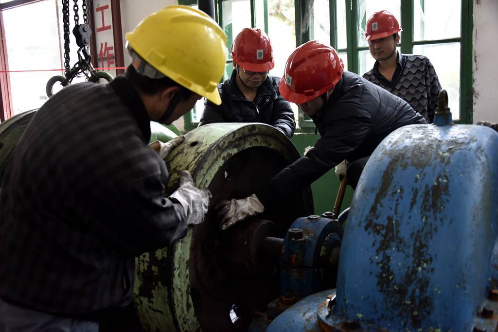
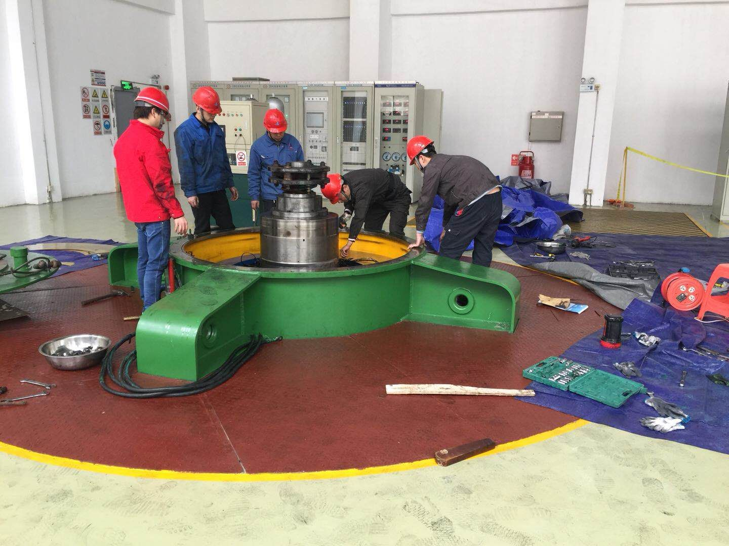
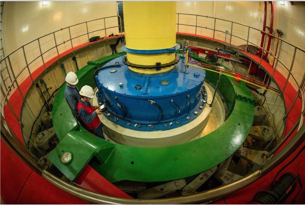
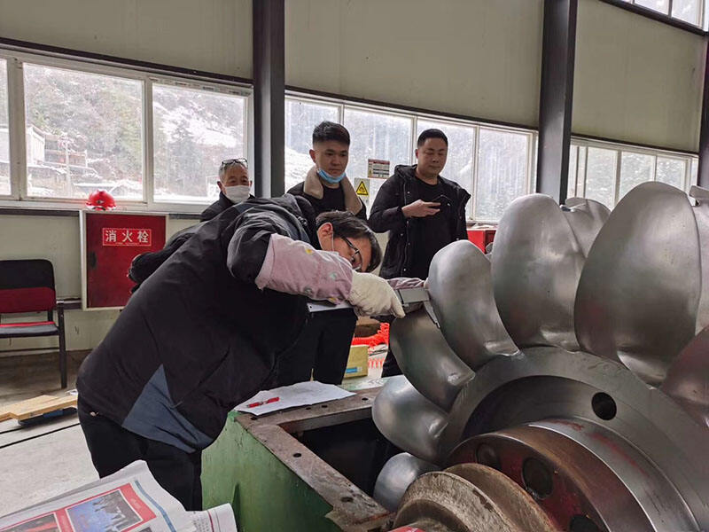
The runner repair was the most time-intensive work needed to get the turbine operational.
Dongturbo Electric Company Ltd. can provide the runner repair service for Pelton turbine runner, Francis turbine runner as well as the Kaplan turbine runner.
