Kawasaki Gas Turbine
Kawasaki offers high-quality gas turbines and gas turbine generator sets designed and produced in accordance with ISO9001 standards, providing customers with the best value and shortest delivery times.
Kawasaki's design and manufacturing capabilities include:
A team of designers, mechanical, electrical, control system, and application engineers with years of experience in design work, as well as complete manufacturing and assembly capabilities for generator sets.
Kawasaki has sold over 12,000 industrial gas turbines, delivering high customer satisfaction globally with their ultra-high reliability and mature after-sales service.
Gas Turbine Generator
The Kawasaki GPB80 is an industrial gas turbine generator with a capacity of 8 MWe, manufactured by Kawasaki Heavy Industries, Ltd. It includes components necessary for generating heat and power, such as the gas turbine, reduction gearbox, couplings, AC generator, starting device, and lubrication system. This gas turbine generator is designed to provide continuous base load power. 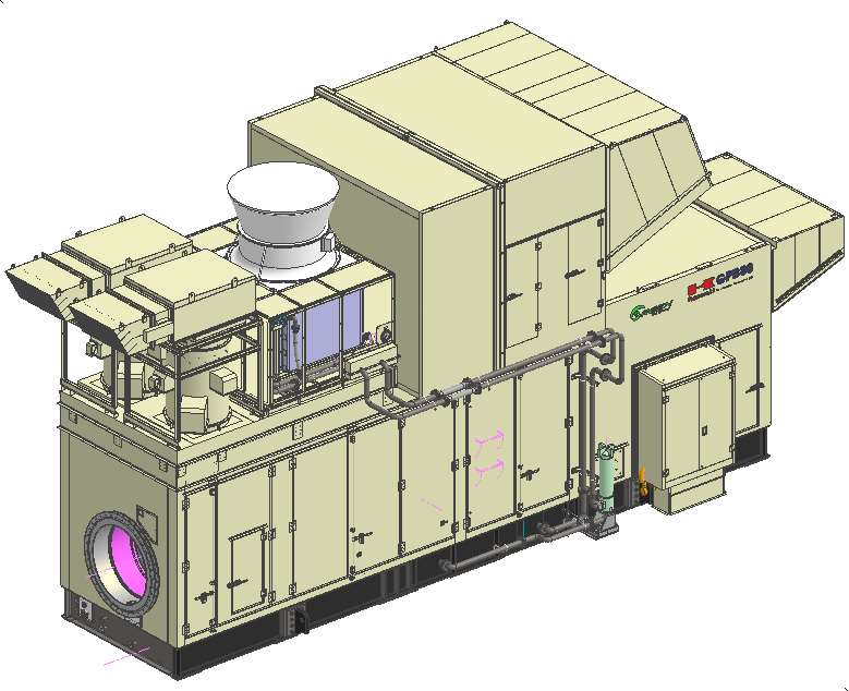
Gas Turbine
A gas turbine is a device that converts thermal energy into mechanical energy. It consists of one or more compressors, a heating device for the working fluid, and one or more turbines. The gas turbine used in the Kawasaki GPB80 gas turbine generator is the M7A-03 model, designed and manufactured by Kawasaki Heavy Industries at its Akashi plant in Kobe, Japan, utilizing the latest technology, characterized by high efficiency and long service life. It employs an open cycle, non-regenerative industrial gas turbine with a single-shaft configuration, suitable for driving generators. The M7A is a relatively mature model in Kawasaki's gas turbine lineup. The first M7A gas turbine was delivered for use in 1994. As of now, more than 200 units of Kawasaki's M7A gas turbines have been delivered worldwide.
Gas Turbine Specifications
- Manufacturer: Kawasaki Heavy Industries, Ltd.
- Model: M7A-03
- Type: Open cycle, no reheat
- Number of Shafts: Single shaft
- Power Turbine Shaft Speed: 13790 rpm
- Dimensions: Length 4.2 [m] x Width 1.5 [m] x Height 1.7 [m]
- Weight: 5.2 [ton]
- Rotation Direction: Counterclockwise (facing away from the output shaft side, towards the output coupling side) 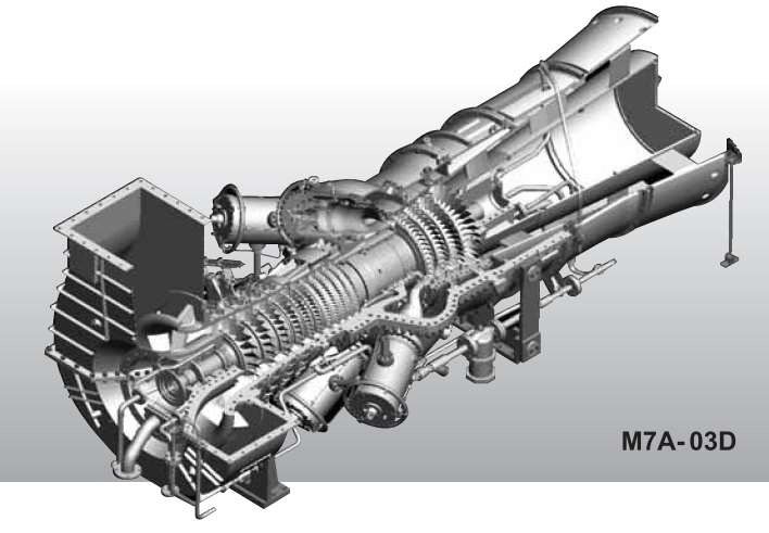
Compressor
The compressor is developed using Kawasaki's mature industrial axial flow compressor technology. The compressor is an 11-stage axial flow type, utilizing hollow wide-chord blades to enhance its own corrosion resistance and blade strength, while improving aerodynamic characteristics.
Visual inspection can be conducted through the inspection port located above the intake collector, replacing the need for disassembly of the main body during maintenance. Additionally, the horizontally split design of the compressor casing facilitates on-site disassembly and inspection during maintenance.
The rotor blades of the first to sixth stages of the compressor are made of titanium alloy, providing high strength and excellent corrosion resistance. The rotor blades of stages 7 to 11, as well as all other stage blades, are made of stainless steel, offering high creep resistance. The rotor tip shroud and the stator inner shroud are made of aluminum wear material, which provides higher adiabatic efficiency by maintaining minimal tip clearance during operation.
The compressor includes inlet guide vanes and variable stator vanes. By changing the angle position of the blades, sufficient surge margin operation is ensured during the start-up process. High efficiency can be maintained during continuous operation.
Compressor Specifications
・ Type: Axial flow
・ Stages: 11
・ Pressure ratio: 16:1
・ Materials: Titanium alloy, stainless steel
・ Inlet guide vanes (IGV): 1st stage
・ Variable stator vanes (VSV): 3rd stage (1st-3rd) 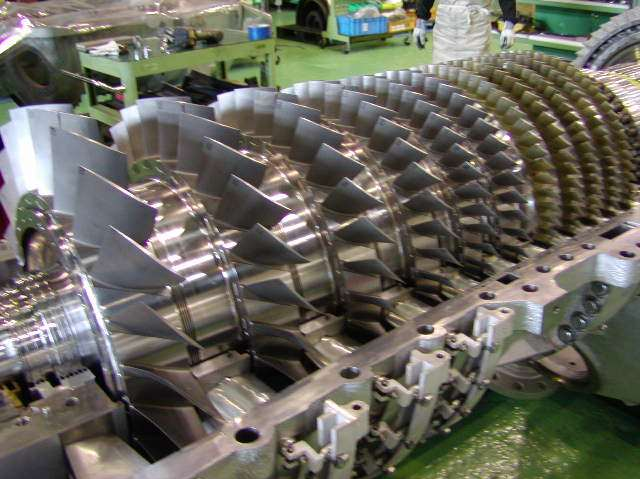
Combustion Chamber
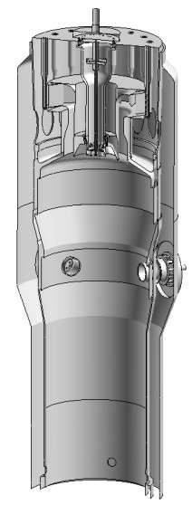
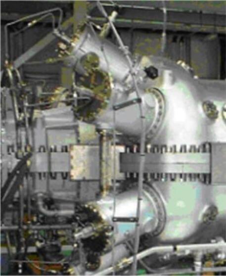
The combustion chamber of the gas turbine is a can-type burner. Using a can-type burner allows for easier disassembly since the burner can be removed for inspection and cleaning without needing to disassemble the main casing. Additionally, the combustion chamber can be removed for bore inspection of the turbine.
The double-wall design of the combustion chamber flame tube achieves effective cooling. Furthermore, the thermal insulation coating on the inner wall can significantly extend its lifespan, and the independent external burner casing makes inspection and maintenance easier.
Combustion Chamber Specifications
・ Type: Can-type
・ Number of Combustion Chambers: 6
・ Emission Reduction Method: DLE (Dry Low Emission)
・ Ignition Method: High Energy Ignition System
・ Weight: 70 [kg] (per combustion chamber)
・ Dimensions: Length 0.4 [m] x Width 0.3 [m] x Height 0.3 [m] (per combustion chamber)
Turbine Component
The rotor of the turbine consists of four discs. They are made from forged nickel-based superalloy. These four discs, along with the coupling rotor, are fixed to the bearings with main shaft bolts to form the turbine body.
Air cooling for the rotor blades and nozzles of the first and second stages is provided internally by the compressor. The cooling efficiency is enhanced by changing the internal cooling structure of the blades and nozzles.
The tips of the first and second stage blades are coated with aluminum abrasive coating. The inner surface of the casing for the third and fourth stage turbine is equipped with honeycomb seals. This design helps to minimize the tip clearance without damaging the blade tips.
Turbine Specifications
・ Type: Axial flow
・ Number of Stages: 4
・ Rotor Weight: 850 [kg] 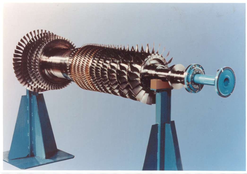
Gearbox (Reduction Gear)
The main function of the gearbox is to reduce the output speed of the gas turbine to the speed required by auxiliary equipment.
The reduction gearbox is specifically designed for Kawasaki's industrial type gas turbines. It utilizes a cylindrical auxiliary gear to extend the overhaul cycle and uses lubrication oil from the turbine lubrication system for lubrication, allowing it to operate continuously with high efficiency. The lubrication oil in the reduction gearbox must maintain stable characteristics under temperature variations and should have good acid and water resistance. The lubrication oil itself must not have any adverse effects on materials such as gears and bearings.
Reduction Gearbox Specifications
- Manufacturer: Hitachi Ltd. Nico Transmission Equipment
- Type: Planetary Gear
- Capacity: 9000 [kW]
- Weight: 6.8 [Ton]
- Dimensions: Length 1.6 [m] x Width 1.6 [m] x Height 1.7 [m] 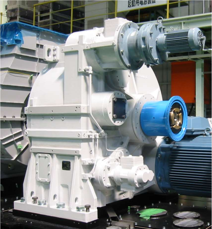
Coupling
The gas turbine, gearbox, and AC generator are connected using couplings to form a coaxial assembly. The high-speed coupling between the gas turbine and the gearbox is of the flexible diaphragm type. The low-speed coupling between the gearbox and the AC generator is a flexible diaphragm type with shear pins. In addition, the coupling protective cover we provide can prevent accidental contact with rotating parts.
Coupling Specifications
・ Manufacturer: Igarashi Industrial Co., Ltd.
・ Type: Flexible diaphragm coupling
・ Mechanical fuse: Shear pin (low-speed coupling)
・ Capacity: 9000 [kW]
Coupling Protective Cover Specifications
・ Type: Cylindrical
・ Material: Carbon steel 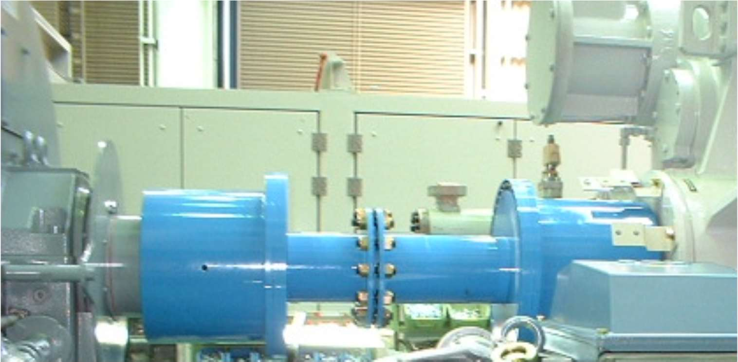
AC Generator
The AC generator driven by a gas turbine converts mechanical energy into electrical energy. The selection of the AC generator should meet customer requirements, and its capacity should exceed the output capacity of the gas turbine under the environmental temperature specified in Section 3 "Site Conditions." The AC generator must be tested according to the manufacturer's established standard inspection plan.
AC Generator Specifications
- Manufacturer: Leroy-Somer, Hyundai, Westinghouse, or equivalent products
- Type: AC synchronous generator
- Capacity: 7500 [kVA] @ 40℃
- Voltage: 11000 [V]
- Frequency: 50 [Hz]
- Phases: 3
- Wires: 4
- Stages: 4
- Speed: 1500 rpm
- Power factor: 0.8 lagging
- Insulation class: H (stator)
- Temperature rise class: F
- Protection class: IP20 or above
- Cooling system: Air-cooled (open air cooling)
- Reference standard: JEC2130 or IEC
Start and Turning Gear System
The starting system provides power to accelerate the gas turbine rotor to the required speed. To prevent bending of the gas turbine rotor, the turning gear system rotates the gas turbine rotor at a very low speed using the starting motor before the engine starts and after the engine shuts down.
The functions of the starting system and turning gear system are provided by the following equipment.
- Four-pole squirrel-cage induction motor (starting motor)
- Variable frequency drive control cabinet (VFD)
Upon receiving the start command, the variable frequency drive control cabinet supplies AC power to the starting motor connected to the gearbox, driving the gas turbine to rotate. The variable frequency voltage provided by the control cabinet allows the starting motor to accelerate to the required speed. When the starting motor reaches the disengagement speed, the one-way clutch engages with the starter shaft of the gearbox. At the same time, the starting motor is disengaged, and the power supply from the variable frequency drive control cabinet is disconnected.
When the gas turbine is shut down, a turning device is required to slowly rotate the turbine shaft to achieve uniform cooling of the turbine shaft. This turning function can be realized through the starting motor and the variable frequency drive control cabinet, while the turning time is automatically controlled by the gas turbine control system.
Starting Motor Specifications
- Manufacturer: Toshiba Mitsubishi Electric Industrial Systems Corporation
- Type: Variable frequency motor
- Rated Power: 180 [kW]
- Voltage: AC 340 [V]
Variable Frequency Drive Control Cabinet Specifications
- Manufacturer: Toshiba Mitsubishi Electric Industrial Systems Corporation
- Input Voltage: AC 380-440 [V], 50 or 60 [Hz]
- Control Cabinet Type: Indoor, non-hazardous area, steel floor-standing
- Protection Level: IP 41