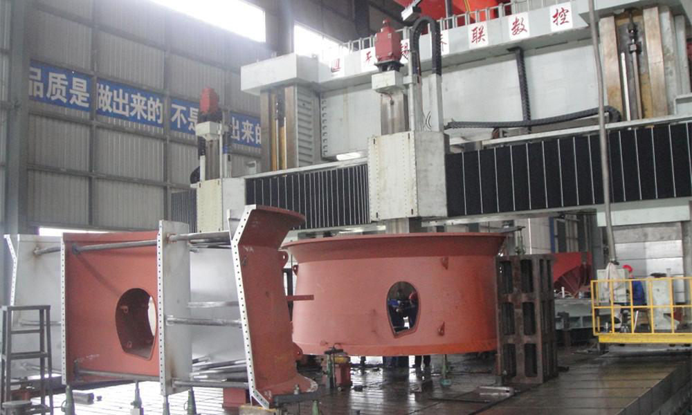
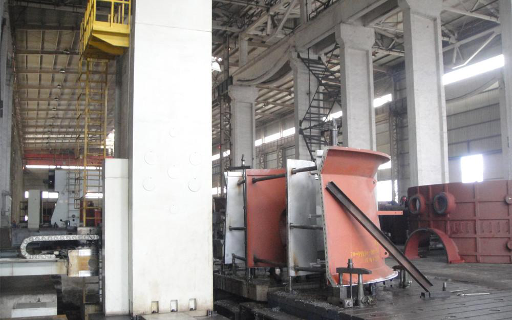
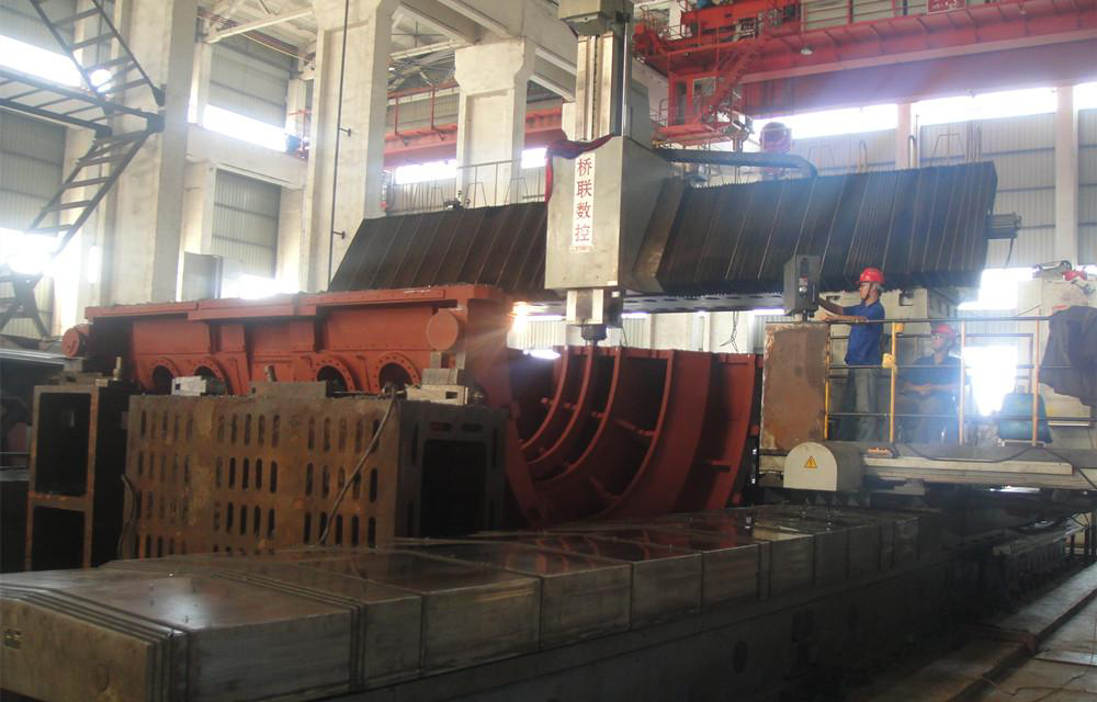
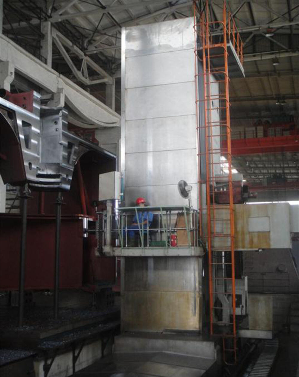
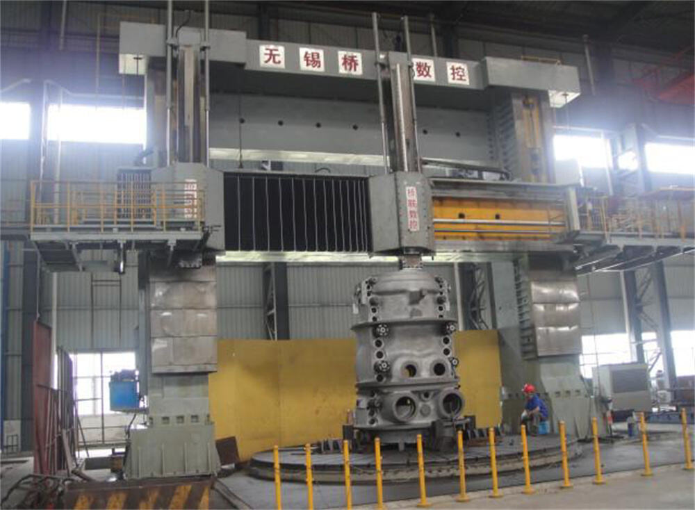
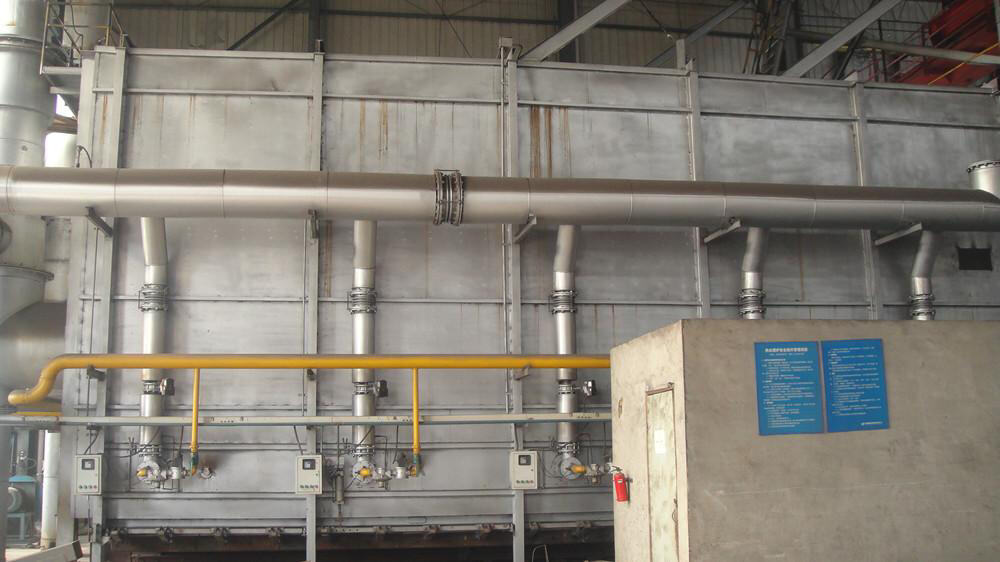
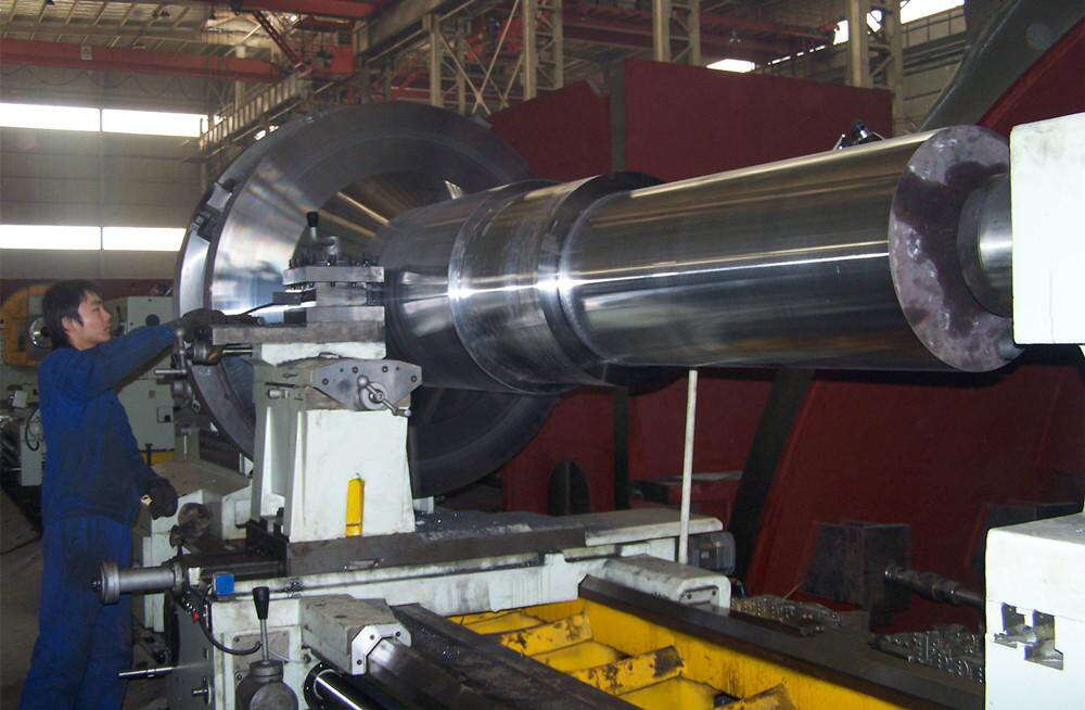
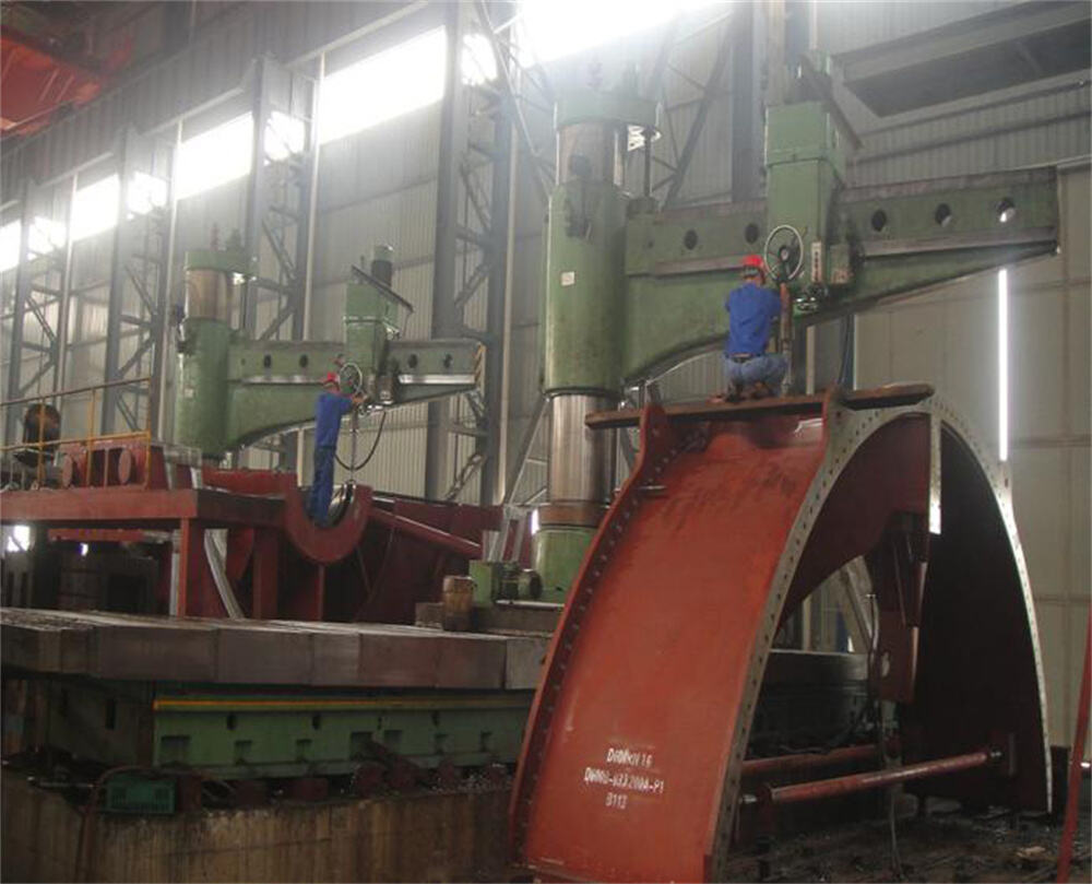
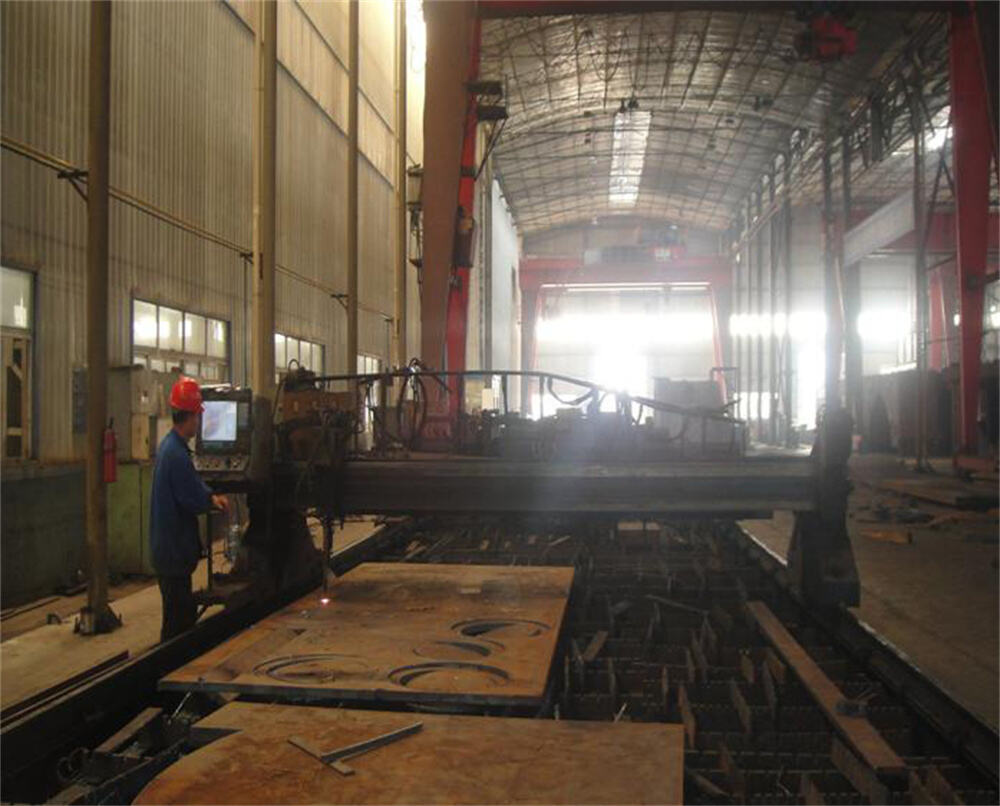
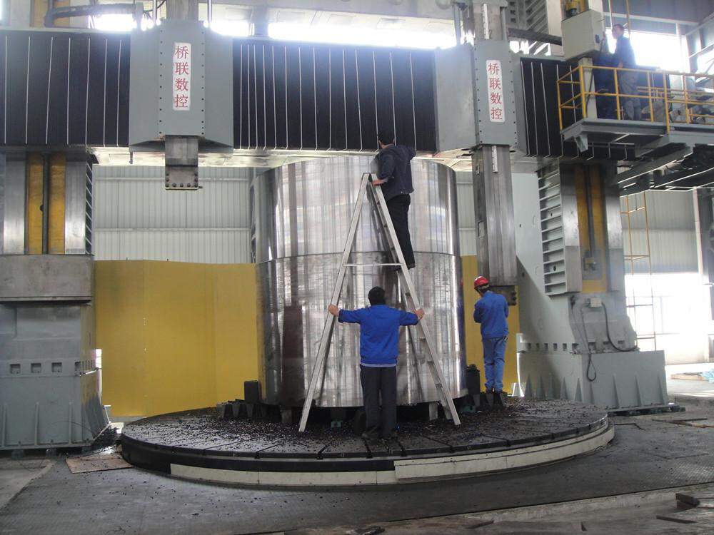
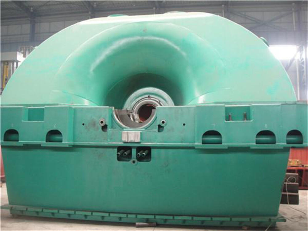
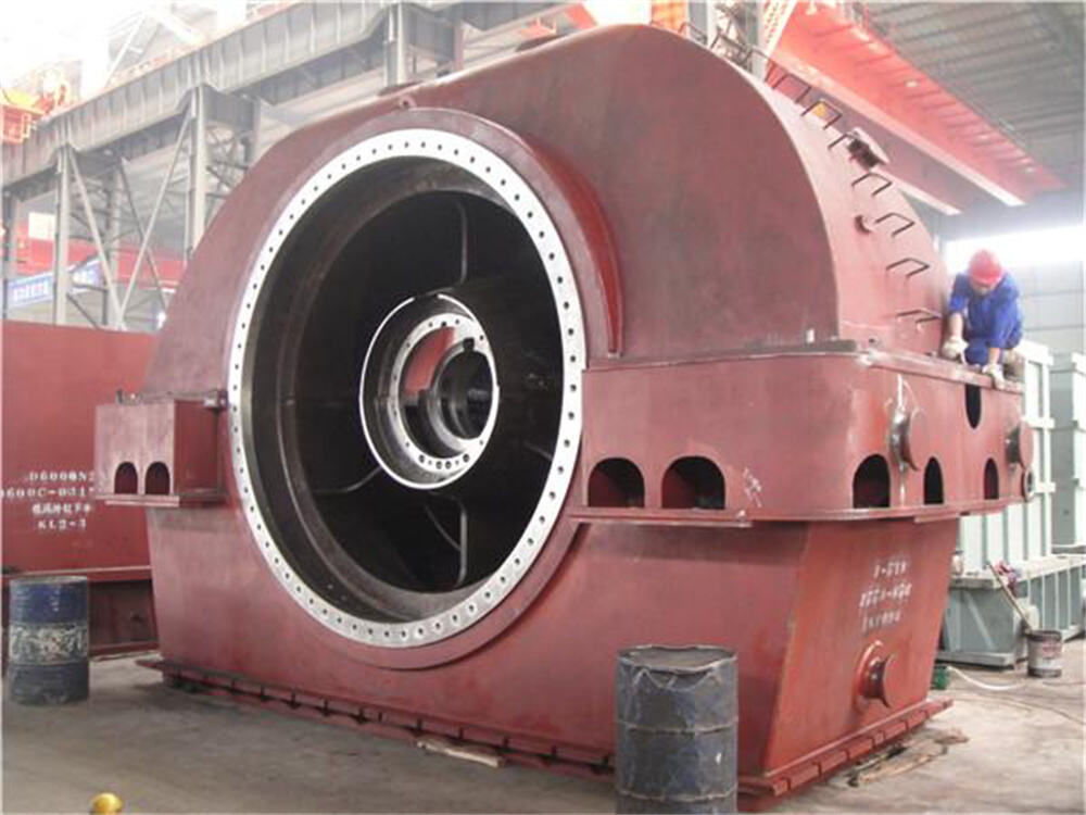
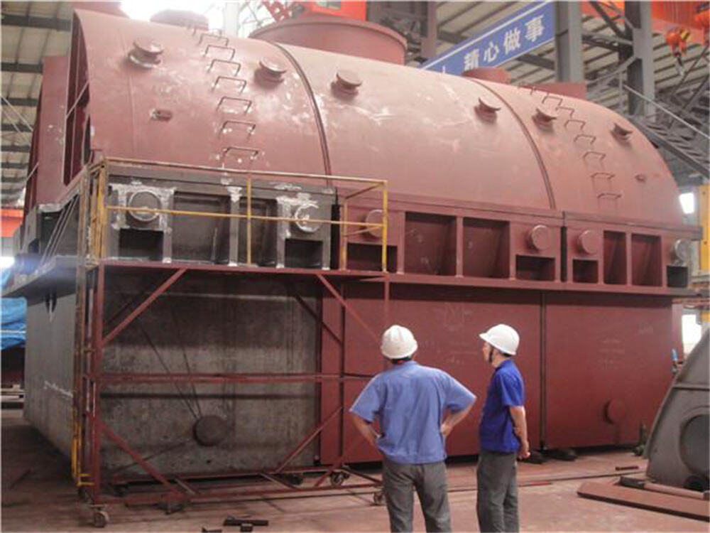
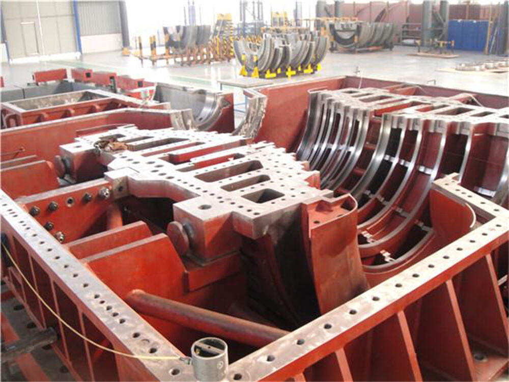
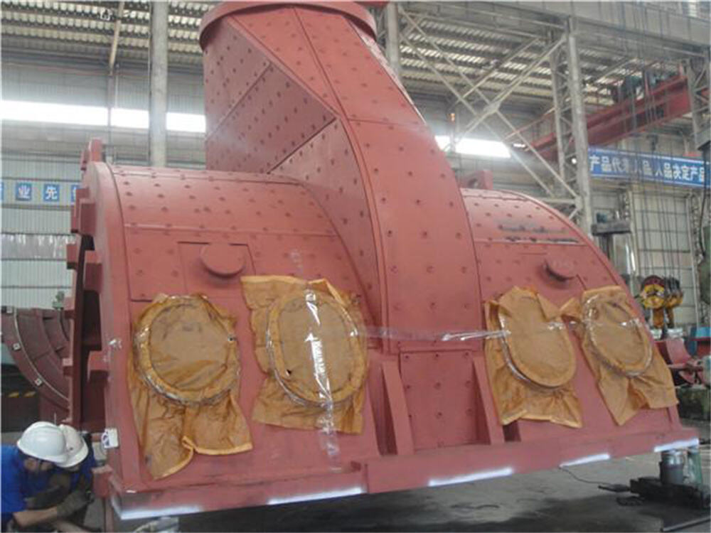
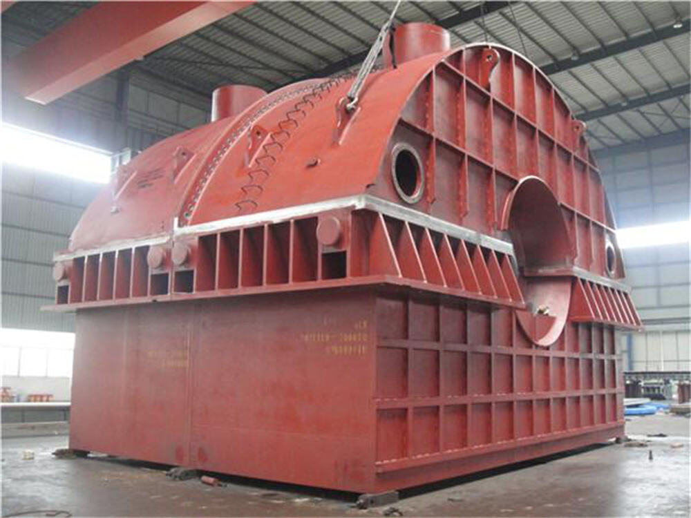
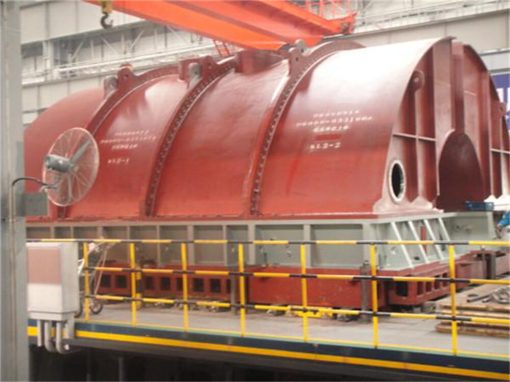
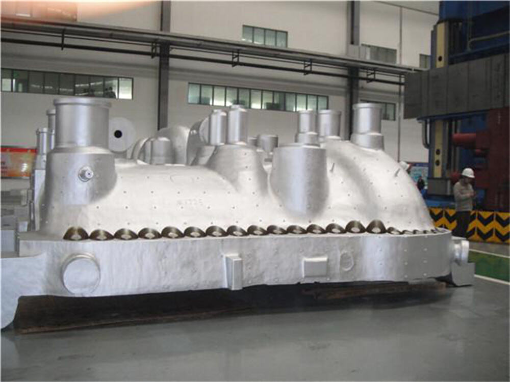
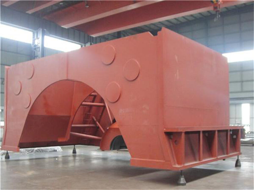
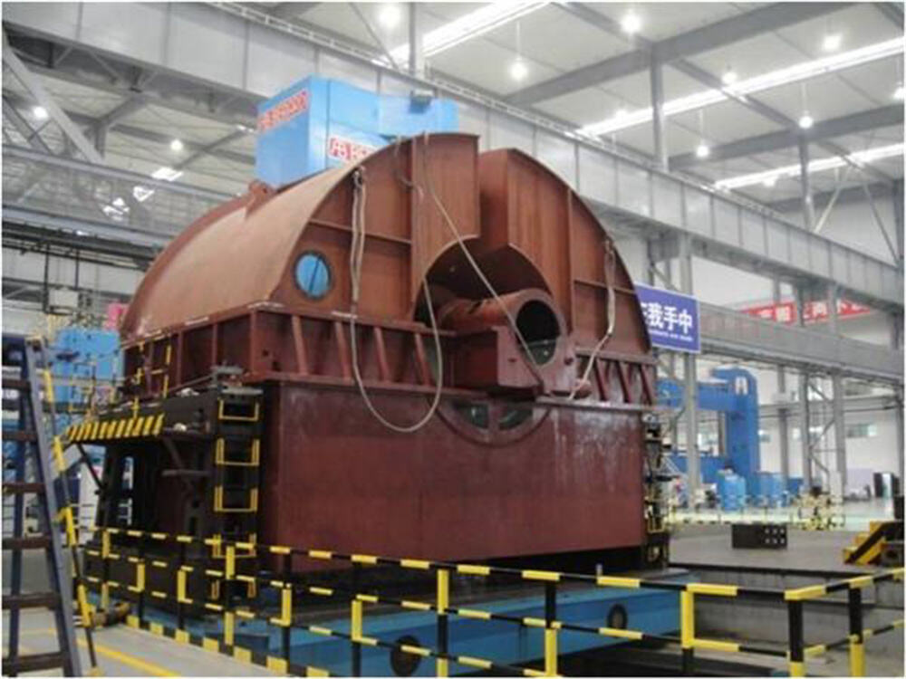
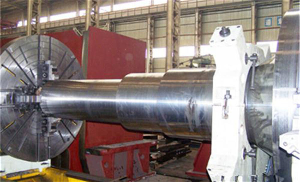
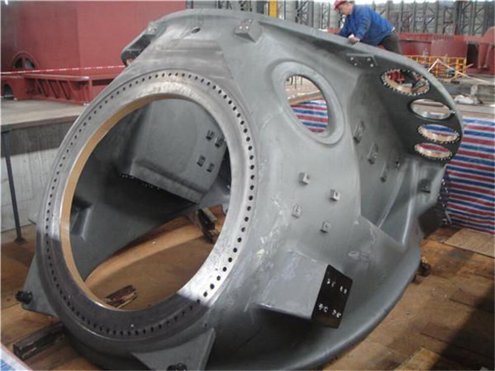
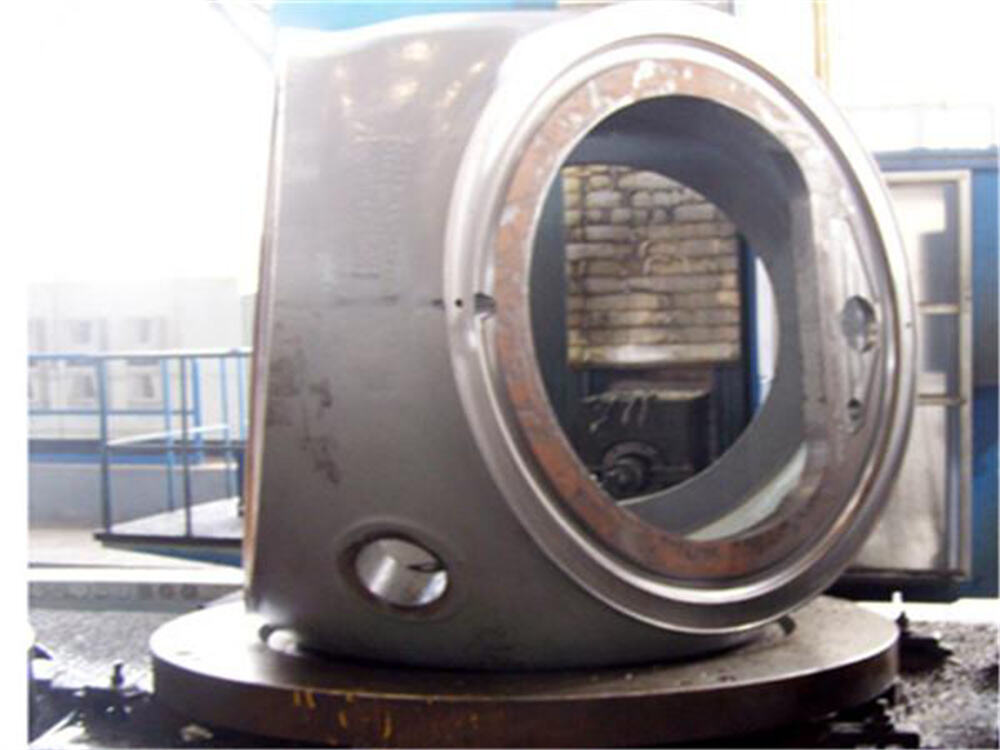
We can retrofit and refurbish existing turbines to improve the service life, operating power, and operating efficiency of the customer's existing turbine to improve the economy of the customer's equipment. Our company has many years of experience in equipment manufacturing, to ensure that the retrofitting program made without affecting the original equipment to achieve performance improvement, and take into account the requirements of environmental protection. We aim to create a more reliable, efficient, energy-saving and environmentally friendly power plant for our customers, improve their production and operation level and reduce maintenance costs, to achieve a win-win situation.
Maintenance & Overhaul In the process of production, the steam turbine may have light or heavy faults, the light ones may affect the production, and the heavy ones may cause safety accidents. Therefore, in the process of electric power production, it is necessary to carry out regular maintenance on the steam turbine, check the running state of the machine, find out the problems in time, use professional technical means to carry out maintenance, and record the faults in time. Through analysis, find out the causes of the faults, sum up experience, find out the key points of the problems, and take effective maintenance or maintenance measures, which can reduce the probability of mechanical faults in future production, ensure the normal operation of the steam turbine, and ensure the production efficiency and safety as far as possible.
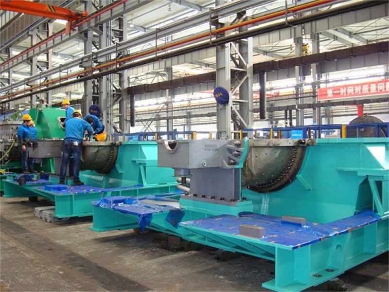
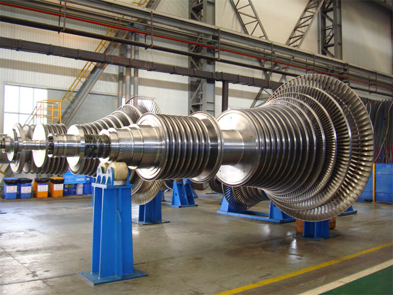
By upgrading and modifying different parts of the steam turbine, the customer will gain the following benefits.
1. Energy saving and consumption reduction to improve the efficiency of the unit.
2. Eliminate the defects existing in the cylinder and improve the reliability and stability of the unit.
3. Reduce operation and maintenance costs.
4. Reduce environmental pollution.
5. Extend the life of the unit.
6. increase the speed of load change of the unit, more flexible to participate in the competition of the power market or heat supply market.
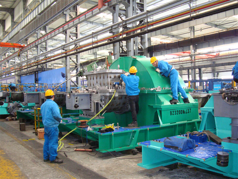
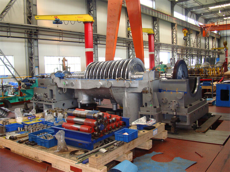
| No | Scope Of Work | |
| 1. | Remove/Install Generator Rotor | |
| A. | Remove Fire Protection Lines | |
| B. | Remove Exciter | |
| C. | Remove Coupling Guard | |
| D. | Split LP Gen Coupling | |
| E. | Check And Record As Found Alignment | |
| F. | Remove Top Half Bearings And Inspect | |
| G. | Remove End Shields And Air Seals TE And GE | |
| H. | Remove Hydrogen Seals | |
| I. | Install Rotor Lifting Device | |
| J. | Remove Bottom Half Bearings #5/#6 And Inspect | |
| K. | Remove Inner Air Seals | |
| L. | Install Rotor Belly Pan | |
| M. | Remove Rotor Lifting Device | |
| N. | Remove Generator Rotor And Place On Stands | |
| O. | Install Rotor Belly Pan | |
| P. | Install Generator Rotor | |
| Q. | Install Rotor Lifting Device | |
| R. | Remove Rotor Belly Pan | |
| S. | Install Inner Air Seals | |
| T. | Install Bottom Half Bearings #5/#6 | |
| U. | Remove Rotor Lifitng Device | |
| V. | Recheck And Record As Built Alignment | |
| W. | Install Hydrogen Seals | |
| X. | Install End Shields And Air Seals TE And GE | |
| Y. | Install Top Half Bearings #5/#6 | |
| Z. | Recouple LP And Gen Rotors & Install Coupling Guard, Install Exciter & Fire Protection Lines | |
| 2. | Thrust Bearing Inspection | |
| A. | Removal Of Front Standard Top Cover | |
| B. | Record Axial Float | |
| C. | Removal Of Thrust Housing Top Cover | |
| D. | Removal And Inspection Of Active And Inactive Thrust Pads | |
| E. | Inspect Mechanical Trip Device | |
| F. | Reinstall Thrust Pads (Active And Inactive) | |
| G. | Install Thrust Housing Top Cover And Record Axial Float | |
| H. | Final Installaton Of Front Standard Top Cover | |
| 3. | Inspection Of Main Lube Oil Pump Casing | |
| A. | Remove Top Cover | |
| B. | Inspect Oil Pump Internals | |
| C. | Check And Record Internal Clearance. Make Adjustments If Needed | |
| D. | Install Top Cover | |
| 4 | Inspection Of Bearing No. 1, 2, 3, & 4 | |
| A. | Removal Of Top And Bottom Half Bearings And Inspect/Record Clearances | |
| B. | Polishing Of Journal | |
| C. | Install Top And Bottom Half Bearings | |
| 5. | Turbine VALVE INSPECTION | |
| A. | Remove GV #1 & #2 And Inspect | |
| B. | Remove RHS Main Stop Valves And Inspect | |
| C. | Remove Of IGV #1 And #2 And Inspect | |
| D. | Removal Of Main Steam Strainer And Inspect | |
| E. | Install GV #1 & #2 Valve | |
| F. | Install RHS Main Stop Valve | |
| G. | Install Of IGV #1 & #2 | |
| H. | Removal Of Main Steam Strainer And Inspect | |
| 6. | HP/IP Turbine Inspection | |
| A. | Remove Manway Doors From LP Outer Casing | |
| B. | Unbolt Crossover Pipe | |
| C. | Remove Partition Wall | |
| D. | Remove Crossover Pipe | |
| E. | Unbolt HP/IP Split Line Bolts | |
| F. | Remove HP/IP Outer Casing | |
| G. | Remove Inner Casing And Diaphragms | |
| H. | Uncouple Rotor From LP Turbine | |
| I. | Record Internal Clearances | |
| J. | Remove HP/IP Rotor | |
| K. | Clean All Components | |
| L. | Re-Install HP/IP Rotor | |
| M. | Remove Bearing NDE And DE Turbine Side A & B | |
| N. | Install Inner Casing And Diaphragms | |
| O. | Align Rotor, Check Clearance And Recouple To LP Turbine | |
| P. | Instal HP/IP Outer Casing | |
| Q. | Install All Split Line Bolts And Fully Torque | |
| R. | Install Crossover Pipe | |
| S. | Install All Flange Bolts And Fully Torque | |
| T. | Reinstate Partition Wall | |
| 7. | TBFP A And B Inspection | |
| A. | Unbolt TBFP A And B Split Line Bolts | |
| B. | Remove TBFP A And B Outer Casing | |
| C. | Uncouple Rotor From The Pump | |
| D. | Remove Bearing NDE And DE Turbine Side A & B | |
| E. | Record Internal Clearances | |
| F. | Remove TBFP A And B Rotor | |
| G. | Clean All Components | |
| H. | Re-Install TBFP A And B Rotor | |
| I. | Install Bearing NDE And DE Turbine Side A & B | |
| J. | Record Internal Clearances | |
| K. | Align Rotor, Check Clearance And Recouple To Pump | |
| L. | Install TBFP A & B Casing | |
| M. | Install All Split Line Bolts And Fully Torque | |
