Table of Contents
1. Overview of TRT Unit
2. Current Operation Analysis of TRT Unit
3. Advanced Technology and Design Method for Optimization and Transformation of TRT Flow Passage
4. TRT Flow Passage Optimization Result
5. On-line Energy Efficiency and Life Analysis Management Intelligence System for Blast Furnace Gas Turbine
6. Optimization and transformation scope of TRT flow passage and compliance with standard
6.1. TRT Flow Transformation Follow Standard
6.2. TRT Flow Transformation and Scope of Supply
7. TRT Transformation Workflow and Cycle
8. measures to prolong leaf life and benefits
9. Quality Assurance and Performance Compliance Assurance
10. after-sales service
10.1. TRT Transformation Site Service
10.2. Long-term TRT Maintenance Service
10.3. Long-term supply of spare parts such as blades
11. Relevant Annex
1. TRT Unit Overview
* * * * * * * * * * * The 1250m3 blast furnace of the company (hereinafter referred to as "* * * * * * Steel") adopts dry bag dust removal, and its matching blast furnace gas turbine TRT uses the residual pressure of blast furnace top gas to generate electricity, bringing huge economic benefits to the enterprise.
The TRT unit was designed and manufactured by Xi 'an Shangu Power Co., Ltd. using Mitsui and Sulzer technologies introduced in its early years. The model number is MPG9.2-280.6/180.Compared with the most advanced TRT technology in developed countries, there is still a big gap in the performance index of domestic TRT units, which is reflected in the efficiency of flow passage. Domestic units are still in the range of 65%~75%, significantly lower than the international advanced level of 84~92%.Therefore, it is necessary to optimize the flow passage of TRT units in operation.
We absorbs the most advanced TRT turbine flow passage design technology from Germany and Japan and applies it to TRT units currently in service in China, which can greatly improve TRT efficiency, i.e. under the existing gas flow rate, pressure, temperature and composition parameters, the generating power of the unit will increase by 10%~20%, creating more economic benefits and contributing to energy conservation and emission reduction.
| Projects | Unit | Operating point | |
| design point | Maximum point | ||
| Local atmospheric pressure | KPa(A) | 100 | |
| Turbine speed | r/min | 3000 | |
| Turbine inlet gas flow | 10,000 Nm3/h | 245000 | 270000 |
| Turbine inlet gas pressure | KPa(G) | 180 | 200 |
| Turbine inlet gas temperature | ℃ | 180 | 230 |
| Gas pressure at turbine outlet | KPa(G) | 10 | 10 |
| Turbine series | - | 2 | 2 |
| Turbine power | KW | 7230 | 9200 |
Table 1 TRT Original Design Parameters | |||
2.Current Operation Analysis of TRT Unit
According to historical operation records, the analysis of the unit's operation on a certain day (as shown in fig. 1) shows that with the fluctuation of inlet flow, the actual operation efficiency value of the unit is between 60-75%.
Fig. 1 operation status of the TRT unit on a certain day (efficiency and inlet flow rate)
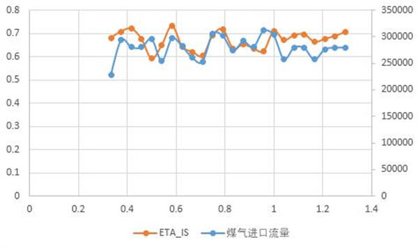
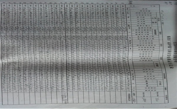
Fig. 2 operation status record of the TRT unit on a certain day
Analysis of the flow capacity at the operating point of this type of unit is as follows:
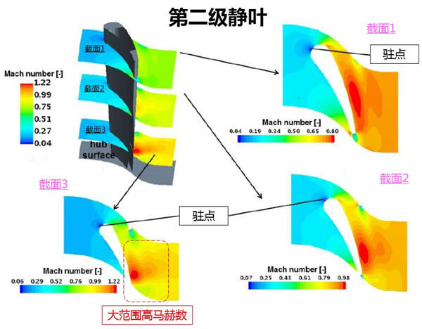
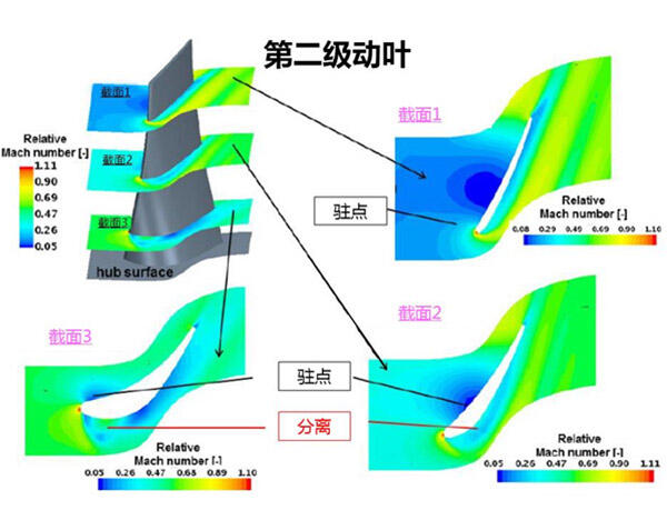
Fig. 3 mach number distribution of this type of unit before through-flow modification
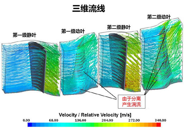
Fig. 4 velocity distribution of this type of unit before through-flow modification
Through the analysis of three-dimensional CFD flow field, it can be seen that the aerodynamic design of static blades and moving blades of this type of unit is relatively backward, and there are many problems in the distribution of airflow: unreasonable velocity and angle distribution, separated flow and backward profile. As shown in fig. 4, the stagnation point of the second stage rotor blade deviates from the leading edge and is located at the front end of the pressure. There is obvious impact angle loss. The high speed region of suction surface increases the flow loss. There are obvious flow separation phenomena on the suction surfaces of the first and second stage rotor blades, resulting in vortex loss and unstable internal flow field. All these have resulted in low flow efficiency and the flow passage needs to be optimized.
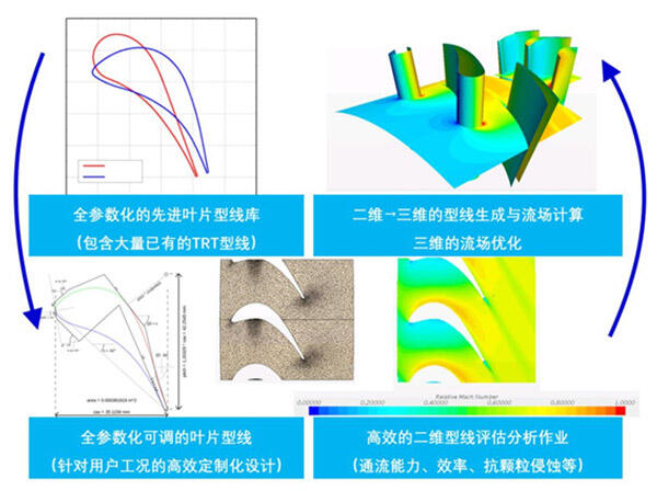
3.Advanced Technology and Design Method for Optimization and Reconstruction of TRT Flow Passage
4.TRT Flow Passage Optimization Results
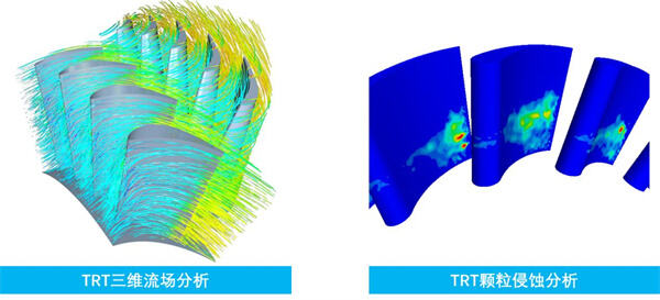
Flow optimization design follows the above-mentioned analysis and design process. Firstly, macro (one-dimensional, two-dimensional) and micro (three-dimensional CFD) calculation and evaluation are carried out on the current unit to analyze the aerodynamic problems of the current unit design. Then combined with the advanced reactive turbine aerodynamic design concept, the flow path arrangement (one-dimensional), vortex control flow pattern (two-dimensional), blade shape and stage matching are gradually deepened and optimized, and finally a reliable aerodynamic design scheme is formed.
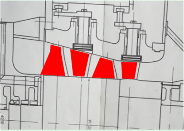
Fig. 5 original meridian plane flow design
Height and Angle Design of Meridian Channel;
-Optimization of axial velocity distribution; -The best blade aspect ratio; -Reducing gap loss;
Blade spacing optimization:
-Reduce secondary flow loss and wake loss;
Radial Vortex Control Redesign;
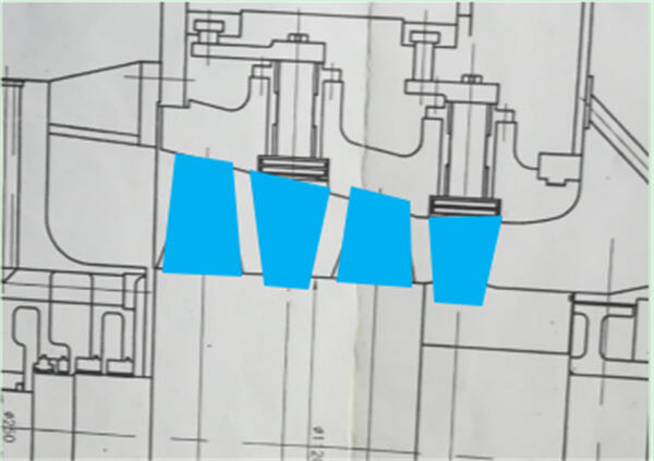
Fig. 6 meridian plane flow design and blade arrangement after optimization of one-dimensional and two-dimensional design
Through one-dimensional and two-dimensional design, a more reasonable meridian plane flow passage design can be obtained, which makes the air flow distribution more uniform, and the enthalpy drop distribution at all levels and the setting of reaction degree tend to be reasonable.The blade aspect ratio, relative pitch and other key geometric parameters affecting aerodynamics are in the best interval. Combining advanced profile and vortex control technology, most of the problems in the original aerodynamic design can be overcome.
Using the optimization methods and methods described above, the following three-dimensional
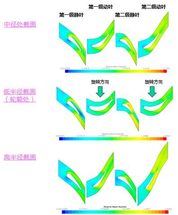
flow field results were obtained under the same inlet parameters
Fig. 7 mach number distribution after flow optimization for units of the same type
As can be seen from the above figure, the impact angle loss is obviously reduced after optimization, and the stagnation point position offset is corrected.There is no longer flow separation in the rotor blades, and the flow distribution in the second stage stator blades is also improved.Generally speaking, the optimized design makes the flow field distribution more uniform and reasonable in both axial and radial directions, reduces the fluid separation, secondary flow loss, impingement angle loss and exhaust loss, and greatly improves the overall efficiency.
The optimized two-stage blade is designed with pure reaction type, and the matching of load coefficient and reaction degree is close to the ideal value, which greatly reduces the residual velocity loss and improves the efficiency of exhaust diffuser.
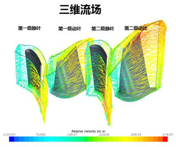
Fig. 8 velocity distribution after flow optimization for units of the same type
| Projects | Unit | Operating point |
| Local atmospheric pressure | KPa(A) | 101.325 |
| Turbine speed | r/min | 3000 |
| Turbine inlet gas flow | 10,000 Nm3/h | 24.5 |
| Turbine inlet gas pressure | KPa(G) | 180 |
| Turbine inlet gas temperature | ℃ | 180 |
| Gas pressure at turbine outlet | KPa(G) | 10 |
| Turbine series | - | 2 |
| Turbine flow efficiency | % | 86.0 |
| Turbine power | KW | 8122 |
| Table 3 TRT Flow Optimization Results | ||
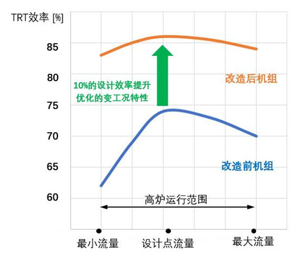
It can be seen from the above that after optimization, the internal efficiency of flow passage reaches 86.0%, with an increase of more than 10%. Under the same inlet conditions (flow rate, pressure, temperature, composition, etc.), the unit output increases 892kW; compared with the design value of 7230kW.According to the industrial average electricity price of 0.65 yuan per kilowatt-hour and the annual utilization of 8000h hours, the annual increase in power generation is 7.316 million kilowatt-hours and the power generation benefit is 4.638 million yuan.
The performance of the TRT unit under variable working conditions (partial load and peak load) is greatly improved, and the efficiency curve is relatively flat compared with the original in a wider variable load range, so that the TRT unit as a whole is in an optimal high-efficiency operation state.
The service life of TRT blades is prolonged, the interval of overhaul periods is prolonged, and the overhaul workload is reduced.
The problems of large blade vibration, high thrust tile temperature and the like of the unit are solved, and the safety and usability of the unit are improved.
5.Intelligent Management System for On-line Energy Efficiency and Life Analysis of Blast Furnace Turbine
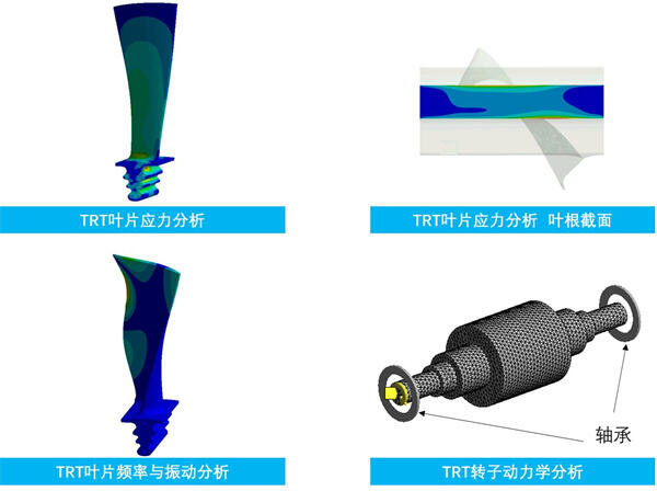
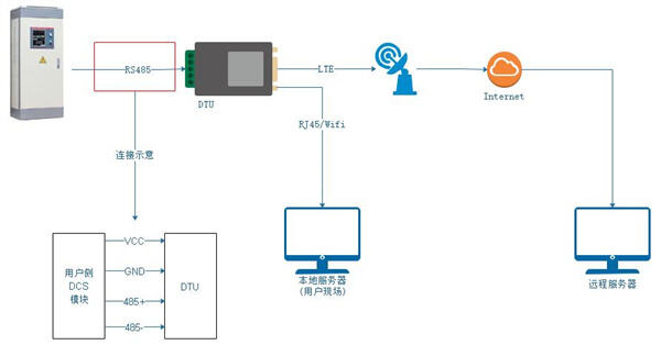
This solution also includes a set of "intelligent system for on-line energy efficiency and life management of blast furnace gas turbine" (TELM+ system). this system can not only analyze the energy efficiency index of gas turbine on-line and in real time, but also generate a large amount of data for operation. through the intelligent algorithm of the system and its own expert system, operation optimization suggestions are given to enable the unit to operate in a higher efficiency point area.However, for the blade dust accumulation and blade erosion missing type, through the embedded intelligent prediction module, the degree of blade dust accumulation and blade missing type are given by artificial intelligence, providing scientific judgment basis for taking corresponding measures.
The system has the capability of machine learning. With the accumulation of operation data, the energy efficiency analysis and life prediction reports automatically generated by the system become more accurate, which greatly facilitates operation and maintenance, makes the operation of blast furnace gas turbine more efficient and healthy, improves the operation rate, and reduces unplanned downtime hours.
6.TRT Flow Passage Optimization Transformation Scope and Compliance Standard
6.1TRT Flow Transformation Following Standards
GBT 28246-2012 "Blast Furnace Gas Energy Recovery Turbine Expander"
GBT 26137-2010 "Thermal Performance Test of Blast Furnace Gas Energy Recovery Turbine Expander"
JB/T4365 "Lubrication, Sealing and Adjusting Oil System"
JB/T9631 "Technical Conditions for Iron Castings of Steam Turbine"
JB/T9637 "Technical Conditions for Turbine Assembly"
GB/T7064 "Technical Requirements for Turbine Type Synchronous Motors"
GB6222 "National Gas Safety Regulations"
YBJ207 "Code for Construction and Acceptance of Metallurgical Machinery and Equipment Installation Engineering" Hydraulic, Pneumatic and Lubricating Systems.
The above-mentioned work shall implement the latest national standards, national technical standards and industry standards.
6.2TRT Flow Transformation and Scope of Supply
According to the user TRT unit model and the actual situation since it was put into operation, the optimization and transformation of flow passage includes the following:
a).Replace all static blades of two stages;
Stator blade design performs multi-round calculation especially for the inlet edge R, which adapts to the wide variation range of inlet angle of attack and ensures high efficiency under various working conditions with wide range before and after the design point.
b).Replace the bearing cylinder;
The cylinder bearing material is QT400-15A, and the center position can be adjusted structurally to make up for manufacturing errors and ensure the coincidence between the center of the shell and the center of the rotor, thus ensuring small and uniform clearance between the blades and the cylinder wall and improving reliability and efficiency.
c).Replace all moving blades of two stages;
The blade has excellent aerodynamic performance, and has the characteristics of no dust accumulation and no blockage.The structure is guaranteed to meet the requirements of strength and vibration.The rotor blade is made of high strength, high temperature resistant stainless steel.The tenon adopts fir-tree type high strength to ensure the fatigue life of the blade.All moving blades are tested for frequency and recorded for reference during maintenance.
d).Replace the rotor (main shaft);
The main shaft adopts high-strength alloy steel 25CrNiMoV integral forging to ensure that the crystal phase structure, physical and mechanical properties of the material fully meet the requirements of TRT operation, and the rotor is subjected to dynamic balance test.
e).Sealing of moving and static blades;
The computer software is used to simulate the working environment, strictly calculate the strain and displacement of the blade in each required state, optimize the tip clearance and root clearance, reduce the loss of air leakage and improve the flow efficiency.
| Serial number | Name | Model/spec. | Quantity/Unit | Remarks |
| 1 | First stage stator | Material 17-4PH | 1 set | |
| 2 | First stage rotor | Material 2Cr13 | 1 set | |
| 3 | Secondary stator | Material 2Cr13 | 1 set | |
| 4 | Second stage rotor | Material 2Cr13 | 1 set | |
| 5 | rotor spindle | 25CrNiMoV | 1 set | Seal with shaft end |
| 6 | Bearing cylinder (upper and lower) and accessoriesGuide ring | QT400-15A | 1 set | Including drive accessories |
| 7 | BPRT/TRT Intelligent System for Online Energy Efficiency Analysis and Life Management | TELM+system | 1 set | Host computer, display |
| MPG9.2-280.6/180 TRT Unit Flow Optimization Transformation Supply Scope | ||||
7.TRT Transformation Workflow and Cycle
Complete all modification work within 6 months from signing the TRT optimization modification contract with the user, and the on-site modification and installation that really affects the operation of TRT shall normally not exceed 10 days.
8.Measures and Benefits of Blade Life Extension
For TRT unit users with high dust content and short blade life, upgrading the blade material (17-4PH) and spraying ceramic coating on the surface can significantly prolong the blade life (more than double the service life), prolong the maintenance cycle interval and reduce the maintenance workload.
17-4PH material (0Cr17Ni4Cu4Nb) is precipitation hardened martensitic stainless steel composed of copper and niobium/columbium, which has high strength, hardness and good corrosion resistance.After heat treatment, the mechanical properties of the product are more perfect, the tensile strength is as high as 890~1030 N/ mm2, the product has good corrosion resistance to acid or salt, and the performance is better than 2Cr13.
| 0Cr17Ni4Cu4Nb | 2Cr13 | |
| stiffiness | 277~311HB | 217~269HB |
| strength of extension | 900~970mpa | 690mpa |
| yield strength | 760~900mpa | 490mpa |
| Table 3 Comparison of Material Properties of Blades 17-4PH/2Cr13 | ||
According to the special working environment of TRT unit blades, the spraying process was improved adaptively, and plasma spraying ceramic technology was applied to the surface anticorrosion of TRT blades.Plasma spraying is a process in which molten material is melted at high temperature by plasma and then the melted material particles are pushed to the surface of parts by means of high-speed gas to form a coating. The thickness of ceramic coating is 0.35 mm. On the basis of ensuring good pneumatic flow efficiency and blade strength, it also has excellent thermal shock resistance and peeling resistance. The surface roughness of the coating is low. The surface roughness of the treated ceramic can reach 0.7μm, which is very smooth. When used in combination with scale inhibitor, the blade life extension effect is obvious.The practice of many TRT users proves that the TRT blades of this process have good wear resistance and corrosion resistance.
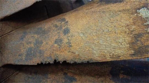
After 7 months of operation
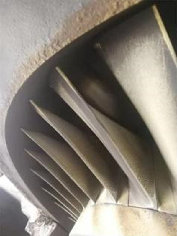
The blade material of the unit is upgraded for 7 months (coated)
By adopting the above-mentioned life extension technology, the blade maintenance period is expected to be extended to 1.5-2 times of the original life, thus reducing the maintenance frequency, saving the maintenance cost, and reducing the loss of power saving benefits of shutdown.
9. Quality Assurance and Performance Standard Assurance
Ensure that the optimization and transformation technology of the flow passage of the boiler gas turbine (TRT) is advanced, safe and reliable, and has similar application performance;
Ensure the quality of the supplied parts, carry out necessary inspections and tests on all parts before delivery, and ensure that the whole design and manufacture meet the requirements of relevant regulations;The materials used are all qualified materials, and can provide corresponding material quality certification documents;
After installation and debugging, the supplied parts reach the safety and reliability required by the standard and meet the performance target value of through-flow modification:
After the optimization and transformation of TRT flow, according to the performance evaluation outline agreed by both parties, under the working condition parameters stipulated in the agreement, the TRT power generation power increase is guaranteed to be greater than 892 kW.
10 After-sales service
10.1 Site service of TRT retrofit
Provide users with efficient and high-quality after-sales service, assign qualified and experienced service managers, regularly report the implementation progress of the renovation project, deliver the parts required for the renovation according to the agreement, and arrange professional on-site technical service personnel/teams to be responsible for on-site installation, commissioning and other technical service projects.After the revamped unit is commissioned and evaluated on schedule, it will provide free technical services within the one-year warranty period.
10.2 Long-term TRT maintenance service
A maintenance team composed of turbine engineers and professionals usually provides maintenance services including:
Open the cylinder to clean the rotor;Repair or replacement of moving blades;Repairing the worn parts of the rotor hub;Replace all sealing pieces on the shaft;Journal repair,
The main shaft journal, thrust plate and blade root groove shall be subjected to color flaw detection.
Rust removal, deformation inspection and repair of worn parts of the bearing cylinder;
Fixed blade repair or replacement, replacement of fixed blade bearings and other accessories;
After the rotor is repaired, high-speed dynamic balance is carried out at a speed of 3000 r/min.
Check the clearance between moving and static blades;
Cylinder bearing sealing strip and positioning pin required for field installation;
TRT Service Required by Other Customers
10.3 Long-term supply of spare parts such as blades
It has the capability of blade production and manufacturing, and has a blade spare parts warehouse. Conventional blades can meet the urgent needs of customers.
11. Relevant annexes
List of major processing and manufacturing facilities
| Type of device | Model | capacity | Workpiece weight | qty | Place of origin |
| XxYxZ | (kg) | (set | |||
| Horizontal machining center (four-axis) | HM630 | 1000x800x850 | 1200 | 1 | Doosan, Korea |
| Vertical machining center(five-axis) | XHK800 | 1250 x400 x400 | 1000 | 1 | China |
| Vertical machining center(five-axis) | HL5001A | Φ800 x320 | 1000 | 1 | China |
| High speed vertical machining center(four-axis) | VF3SS/VF3/VF4 | 1016 x508 x635 | 800/1600 | 6 | Haas, USA |
| Vertical machining center(four-axis) | VM1300A | 1300 x650 x710 | 1500 | 2 | China |
| Vertical machining center(four-axis) | BV100 | 1050 x510 x560 | 700 | 2 | China |
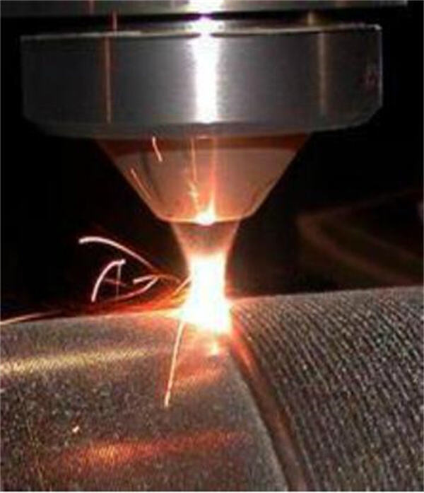
| Laser cladding system | RC-LCD-800W | Fixed/movable | 1500/30000 | 1 | China |
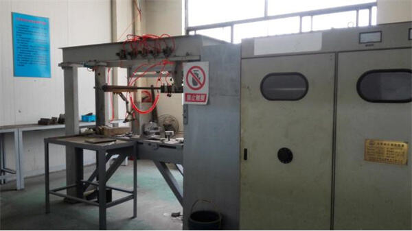
| Stellite Welding/High Frequency Quenching System | GGC-80-2 | 1500 x500 x500 | 500 | 1 | China |
| Abrasive belt grinding/polishing machine | 2M5430 | Φ200 x50 | 50 | 12 | China |
Numerical control machine tool group
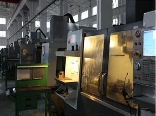
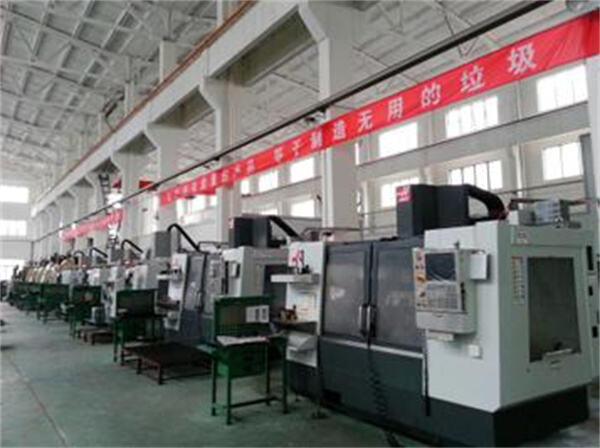
Laser cladding system
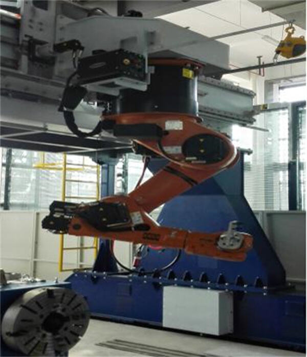
Stellite Welding/High Frequency Quenching System
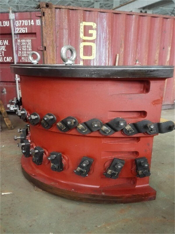
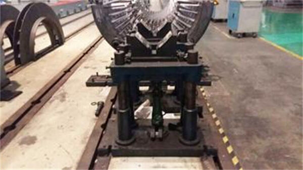
Rotor installation and maintenance device
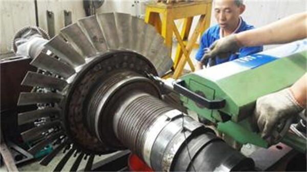
Abrasive belt grinding and polishing machine group
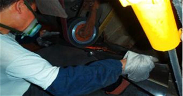
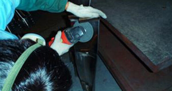
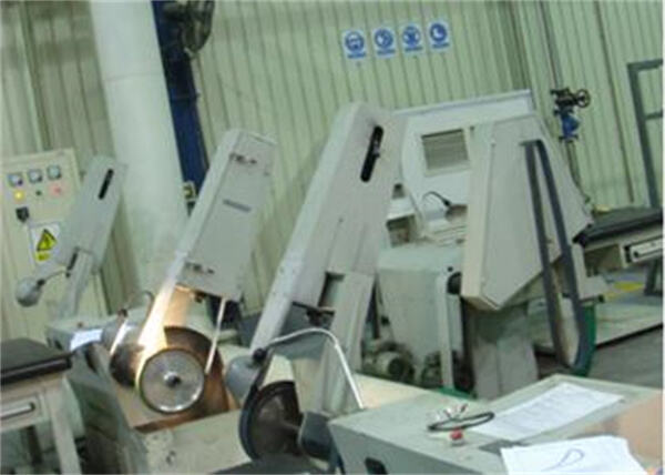
| Device type | Model | measuring range | Quantity | Place of Origin | |
| XxYxZ | (Taiwan) | ||||
| Coordinate measuring machine | X08107 | 800x1000x700 | 1 | Wenze, Germany | |
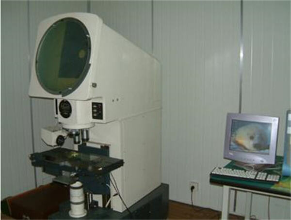
| 50x projector | JT36-500 | 200 x100 x70 | 1 | Xintian Optoelectronics | |
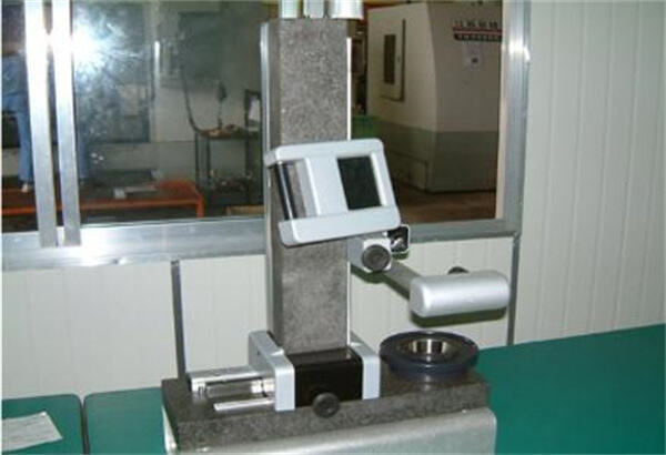
| Tool measuring instrument | E238 | Φ280 x380 | 1 | ELBO, Italy | |
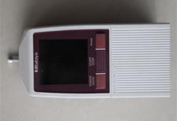
| Roughness measuring instrument | SJ-210 | 1 | MITU, Japan | ||
| Frequency testing system | FSA-C | 200-1200 | 1 | Xi'an Jiaotong University | |
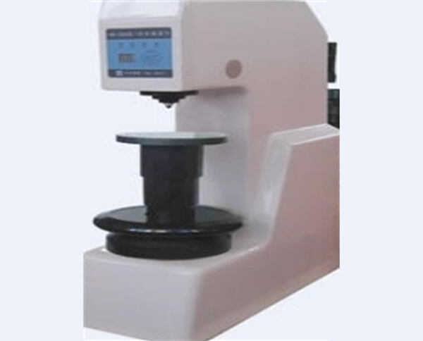
| brinell hardness tester | HB-300B | 1 | Beijing era | ||
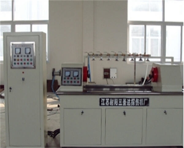
| Nondestructive testing machine | CJW-2000I | 0-1500 | 1 | Jiangsu Sanshengda | |
| Spectrum analyzer | WX-5 | 1 | Tianjin jinfei | ||
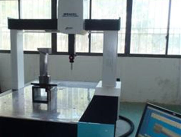 |
 |
||||
| Coordinate measuring machine | 50x projector | ||||
 |
 |
||||
Tool measuring instrument |
Roughness measuring instrument |
||||
 |
 |
||||
Magnetic particle flaw detecto |
Magnetic particle flaw detector |
||||
11.1 List of Customers
Supplier of the main turbine
Shaanxi Blower (Group) Co., Ltd.
Chengdu Engine (Group) Co., Ltd.
Nanjing Turbine Motor (Group) Co., Ltd.
Harbin Steam Turbine Factory Co., Ltd.
Dongfang steam turbine co., ltd
Beijing North Heavy Duty Truck Motor Co., Ltd.
……
End customer
Hebei Iron and Steel Co., Ltd.
Shandong Iron and Steel Group Co., Ltd.
Jiangsu Shagang Group Co., Ltd.
Lianfeng Steel (Zhangjiagang) Co., Ltd.
Changzhou Zhongtian Steel Group Co., Ltd.
Gansu Jiugang Group Company
China Datang Group Corporation
China Resources Electric Power Holding Co., Ltd.
……
11.2 Experience
Dismantling and Repairing of 6# Rotor Bearing Steel of Zhongtian Steel
Repair of No.10 Rotor of Zhongtian Iron and Steel Company by Dismantling and Assembling Bearing Steel
Zhongtian Steel's 7#BPRT Rotor Dismantles and Replaces Blades, Repairs Rotor Bearing Cylinder
Shagang group huasheng ironmaking 2#TRT rotor disassembly and replacement of a full set of dynamic and static blades, rotor bearing cylinder gland laser cladding
Shagang group huasheng ironmaking 7#TRT rotor disassembly and replacement of a full set of dynamic and static blades
Manufacturing, Assembly and Commissioning of Sliding Oil Pump Steam Turbine of CSIC
Tangshan Ruifeng Steel MPG9.7BPRT Rotor Bearing Cylinder Disassembly and Overhaul
Rotor Assembly of Shagang First Coking 18MW Industrial Steam Turbine
Shandong Huantai Thermoelectric 25MW High Temperature and High Pressure Steam Turbine Rotor Disassembly and Assembly Blade
Disassembly and Repair of TRT Rotor in Jinan Steel 3200 Blast Furnace
Disassembling and Assembling Last Stage Rotor of Changqiang Steel Turbine
Jiuquan Steel 3#TRT Rotor Dismantle and Replace Blades
Mapping and Manufacturing of Disassembly and Assembly Blades for TRT Rotor of "MAN Turbine" in Benxi Steel
Optimization of Low Pressure Rotor of Datang Baoding Thermoelectric 8#9#125MW Steam Turbine
Optimization of Jining Jinwei 50MW Combined Cycle Steam Turbine
Optimization of 50MW Combined Cycle Steam Turbine in Beian Thermal Power Plant
Reconstruction of 100MW Steam Turbine in Hulinhe Power Plant
Optimization of 25MW Steam Turbine Rotor Blade in Lianfeng Steel
Optimization of 3#BPRT Rotor Blade in Lianfeng Steel
Optimization of 6#TRT Rotor Blade in Lianfeng Iron and Steel Company
Optimization of 4#BPRT Rotor Blade in Lianfeng Steel
Optimization of 7#TRT Rotor Blade in Lianfeng Iron and Steel Company
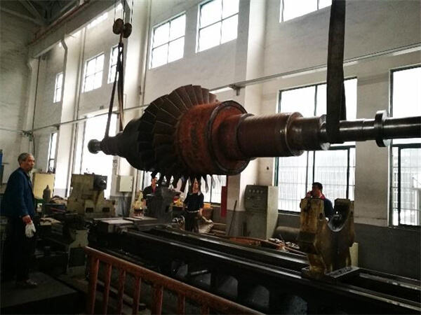
11.3 Related photos
