Biomass and MSW Receiving System
Biomass and MSW is loaded by a collection vehicle from a Biomass and MSW collection point or a Biomass and MSW transfer station and then sent to a Biomass and MSW incineration plant for crushing on a platform in front of a sealed Biomass and MSW warehouse. Then the crane grab will transport the Biomass and MSW to the Biomass and MSW storage pit.
| Serial number | Name | Specifications | Remarks |
| 1 | Double shaft crusher | Processing capacity: | |
| 2 | Magnetic separator | Magnetic field strength: | |
| 3 | Belt conveyor | The length is determined according to the actual demand. | |
| Table 3-1 Main Equipment Specifications | |||
Biomass and MSW storage system
The Biomass and MSW is discharged into the Biomass and MSW storage pit through the discharging gate, and the pit stores the Biomass and MSW treatment capacity for at least about 10 days. When necessary, the Biomass and MSW can also be piled up in a triangular shape along the wall opposite to the input gate by using a one-sided stacking method to increase the capacity of the Biomass and MSW storage pit.
In order to prevent the Biomass and MSW entering the incinerator from mixing with incombustible Biomass and MSW or Biomass and MSW with too high moisture content, the Biomass and MS
W storage pit shall be composed of a good Biomass and MSW leachate grid interlayer and an impervious pool bottom plate with reinforced concrete structure. The bottom of the pit shall have a certain slope to four sides, and a Biomass and MSW leachate drainage port shall be arranged at the side wall about 0.6 meters from the bottom of the pool, and 2-5 drainage ports shall be arranged on the drainage side. The Biomass and MSW leachate from each drainage port shall be discharged to the Biomass and MSW leachate collection pool through pipelines.
The Biomass and MSW storage area is completely closed, requiring the Biomass and MSW storage area to be in a slightly negative pressure working state, so as to reduce odor escape generated during Biomass and MSW storage. At the same time, in order to prevent the breeding of mosquitoes, flies and bacteria, chemical spraying facilities are set up in the storage pit, and chemicals are sprayed regularly for sterilization and disinfection in summer.
Biomass and MSW Feeding System
The pre-stored Biomass and MSW is hoisted into the hopper by the crane grab bucket and pushed into the pyrolysis gasification furnace evenly and horizontally by the hydraulic feeder.
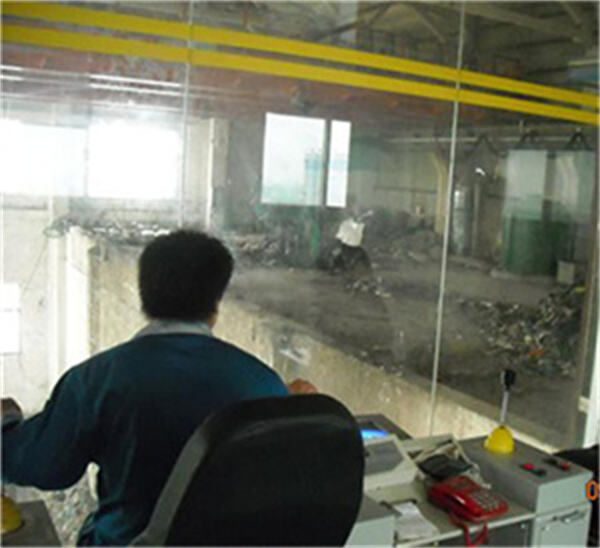
The grab crane is a special bridge crane. The crane operation room is equipped with a closed observation window with safety protection, and has an independent ventilation and filtration system. The operation room is equipped with an industrial television monitoring system, which enables the operator to determine the position of Biomass and MSW in the bin.
The grab crane is operated remotely by the operator in the operating room at the middle position of the upper part of the Biomass and MSW storage pit. At the same time, the limit switch, a safety measure to prevent crane collision, is set to prevent the grab from colliding with the hopper or other facilities.
The operation control of all actions of the Biomass and MSW crane and grab bucket is completed in a special operation control room. The side of the Biomass and MSW crane operation room facing the Biomass and MSW storage pit is transparent, so that the crane driver can directly observe the whole picture of the Biomass and MSW storage pit, including the opening and closing of the Biomass and MSW discharge gate, the distribution of Biomass and MSW in the storage pit, the operation of the crane and grab bucket, and the feeding inlet of the Biomass and MSW pyrolysis gasification furnace.
For the key parts of the feed inlet and Biomass and MSW storage pit of the Biomass and MSW incinerator, cameras are set to transmit monitoring signals to the monitoring screen of the crane control room.
In this project, an electric overhead crane is used to grab the Biomass and MSW. Its function is not only to feed the Biomass and MSW pyrolysis furnace, but also to mix the Biomass and MSW in the Biomass and MSW pit evenly. Semi-automatic control is adopted to reduce the labor intensity of operators. The grab crane is provided with a limiting device to prevent the grab bucket from colliding with the wall of the Biomass and MSW pit.
| Serial number | Parameter name | Unit | Design value |
| 1 | Crane type | -- | Electric bridge |
| 2 | Lifting capacity | Ton | |
| 3 | Crane span | Meter | |
| 4 | Track length | Meter | |
| 5 | Maximum lifting height | Meter | |
| 6 | Lifting vertical speed | Meters per minute | |
| 7 | Trolley speed | Meters per minute | |
| 8 | Cart speed | Meters per minute | |
| 9 | Work level | Level | |
| 10 | Total weight of equipment | Ton | |
| 11 | Total crane power | kW | 15 |
| Table 3-2 Technical Parameters of Cranes in Waste Incineration Plant | |||
Note: crane specifications and dimensions are determined according to the actual conditions of the project. | |||
Pictures of engineering examples

Crane Biomass and MSW

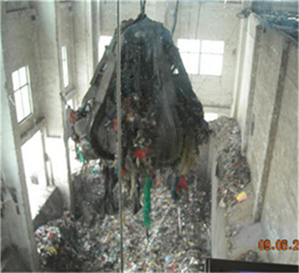
Biomass and MSW grab status

Crane Operation Room

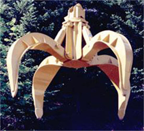
Bridge Grab
| Serial number | Parameter name | Unit | Design value |
| 1 | Grab volume | m3 | |
| 2 | Grab closing time | second | |
| 3 | Grab opening time | second | |
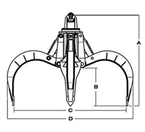
| 4 | Grab fully open dimension (D) | m | |
| 5 | Grab fully closed height(A) | m | |
| 6 | Grab power | kW | |
| 7 | Grab weight | Ton | |
| Table 3-3 Grab Parameters | |||